EV-020 Rev. 11 – 2014
17
Installing the magnet on the anchor windlass
• A hole having a diameter of 6.5 mm (~1/4”) and depth of 8 mm (5/16”) must be drilled on a tooth
of the gipsy, in a place outside the chain’s path.
• In the case of vertical shaft anchor windlasses (see Fig. 1B), drill the hole in the lower
circumference of the gipsy.
• In the case of horizontal shaft anchor windlasses (see Fig. 2B), drill the hole in the outer
circumference of the gipsy.
• Also make sure that the protruding part of the magnet will not collide with the base or sensor
during rotation of the gipsy.
• Insert the metal part of the magnet in the hole, allowing the protected part to protrude by about 2
mm. Fix it in place using an adhesive for metals (two-component epoxy glue) or silicone. The
glue used must be able to withstand a marine environment.
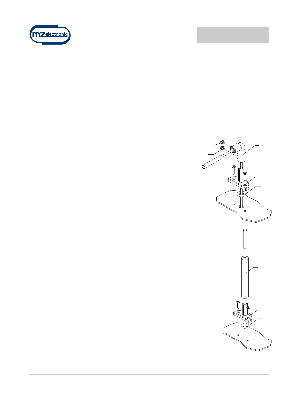
Installing the magnetic sensor for vertical shaft anchor
windlasses
(see Fig. 1A – 1B)
• Drill a 4 mm (~3/16”) hole in the cover through which to thread the
sensor cable.
• Fasten Part A of the support with the two screws provided, after
having positioned the O-ring in the lower part of the support.
• Fit Part B with the magnetic sensor on support A and adjust its
height until it is aligned with the magnet fastened on the gipsy.
• Bring the sensor to a distance of about 3 mm (~1/8”) from the
magnet and secure it in place by tightening screw G1. Then tighten
screw G2.
Installing the magnetic sensor for horizontal shaft anchor
windlasses
(see Fig. 2A – 2B – 2C)
• Drill a 4 mm (~3/16”) hole in the cover through which to thread the sensor
cable.
• Fasten Part A of the support with the two screws provided, after having
positioned the O-ring in the lower part of the support.
• Cut Part C to measure using a hacksaw. The sensor must be positioned at a
distance of about 3 mm (~1/8”) from the magnet.
• Fit Part C with the magnetic sensor on support A and fix it in place using an
adhesive for plastic (two-component epoxy glue) or silicone.
• Using the same glue, attach the sensor to Part C.
Installing the chain counter
(see connection diagram)
C
A
OR
OR
A
B
G1
G2