EasyManua.ls Logo

Nabco GT-8710 User Manual

Default Icon
32 pages
To Next Page IconTo Next Page
Page #1 background imageLoading...
Page #1 background image
S82 W18717 Gemini Drive
Muskego, Wisconsin 53150
Phone: (877) 622-2694
Fax: (888) 679-3319
www.nabcoentrances.com
Technical Support: (866) 622-8325
Part #C-00084
Rev. 9/09/16
WARNING
• Turn OFF all power to the Automac Door if a Safety System is not working.
• Instruct the Owner to keep all power turned OFF unl correcve acon can be achieved by a NABCO
trained technician. Failure to follow these pracces may result in serious consequences.
• NEVER leave a Door operang without all Safety detecon systems operaonal.
Swing Door Operator
Wiring and Adjustment Manual
** with Magnum 4A Control*
DN 0557
LED
TRANSFORMER
AUX
PWR
J2
J5
AC IN
SW2
SW1
F1
RELAY
RELAY
J4
TDAS
SIGNAL
INPUT
TDPG
LCHK
CLOSE
Fuse 1: 0.5A 24 VAC
STOP
OPEN
BCHK
CURRENT
LIMIT
MOTOR
J1
R28
MAGNUM 4A
F2
Fuse 2: 5
A
120/240
Capacitor
MO
V
1234O
F
F

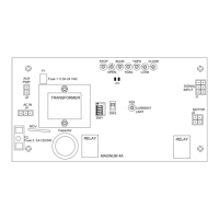
Table of Contents

Questions and Answers:

Nabco GT-8710 Specifications

General IconGeneral
BrandNabco
ModelGT-8710
CategoryGate Opener
LanguageEnglish

Summary

General Safety Recommendations

Electrical Connection DANGER

Disconnect all power before making electrical connections to avoid shock or fatal injury.

Chapter 2: Getting Started

Section 2a. Features

Lists capabilities and functionalities of the Magnum 4A Control, including replacements and programming.

Chapter 3: Magnum 4A Board Terminals

Chapter 4: Adjustments and Status LEDs

Section 4b. Dip Switch Bank (SW1)

Details the function and settings of the 4-position dip switch bank for Safety, Push-N-Go, modes.

Section 4b. Potentiometer Adjustments

Describes the location and adjustment method for the 8 potentiometers (Stop, Open, BCHK, etc.).

Chapter 5: Connect Incoming 120 VAC Wires

Chapter 6: Wiring Safety Devices

Section 6a. Panic Breakout Latch/Switch (Open Loop)

Explains connecting panic latch switch for breakout and operator microswitch to shut unit off.

Section 6b. Panic Breakout Latch/Switch (Closed Loop)

Details the 'Fail Safe' safety circuit feature and how the Panic Breakout Switch activates it.

Chapter 7: Wiring Diagrams (General)

Chapter 8: Wiring Diagrams (Accessories)

Chapter 9: Troubleshooting

Operator Does Not Function

Addresses issues like blown fuses, no incoming power, or improper motor circuit connection.

Door Slams Closed

Covers causes like incorrect back check or closing speed adjustments on the control.

Motor Issues

Includes motor blown, open circuit, or incorrect wiring causing no door movement.

Safety Circuit Issues

Troubleshoots activated safety circuits or improper activation circuit connections.

Back Check Adjustment Issues

Covers problems with back check adjustment having no effect or no back check present.

Door Not Staying Closed

Addresses issues like improper preloading or excessive building stack pressure.

Safety Sensor Malfunctions

Diagnoses issues where safety sensors do not function or are improperly connected.

Activation Signal Issues

Addresses cases where activation signals are sent but the door does not open.

Simultaneous Pair Activation

Troubleshoots one sensor not activating both doors on a simultaneous pair.

Related product manuals