Page 13 www.NabcoEntrances.com 04-24-08
U30 Electrical Installation Manual
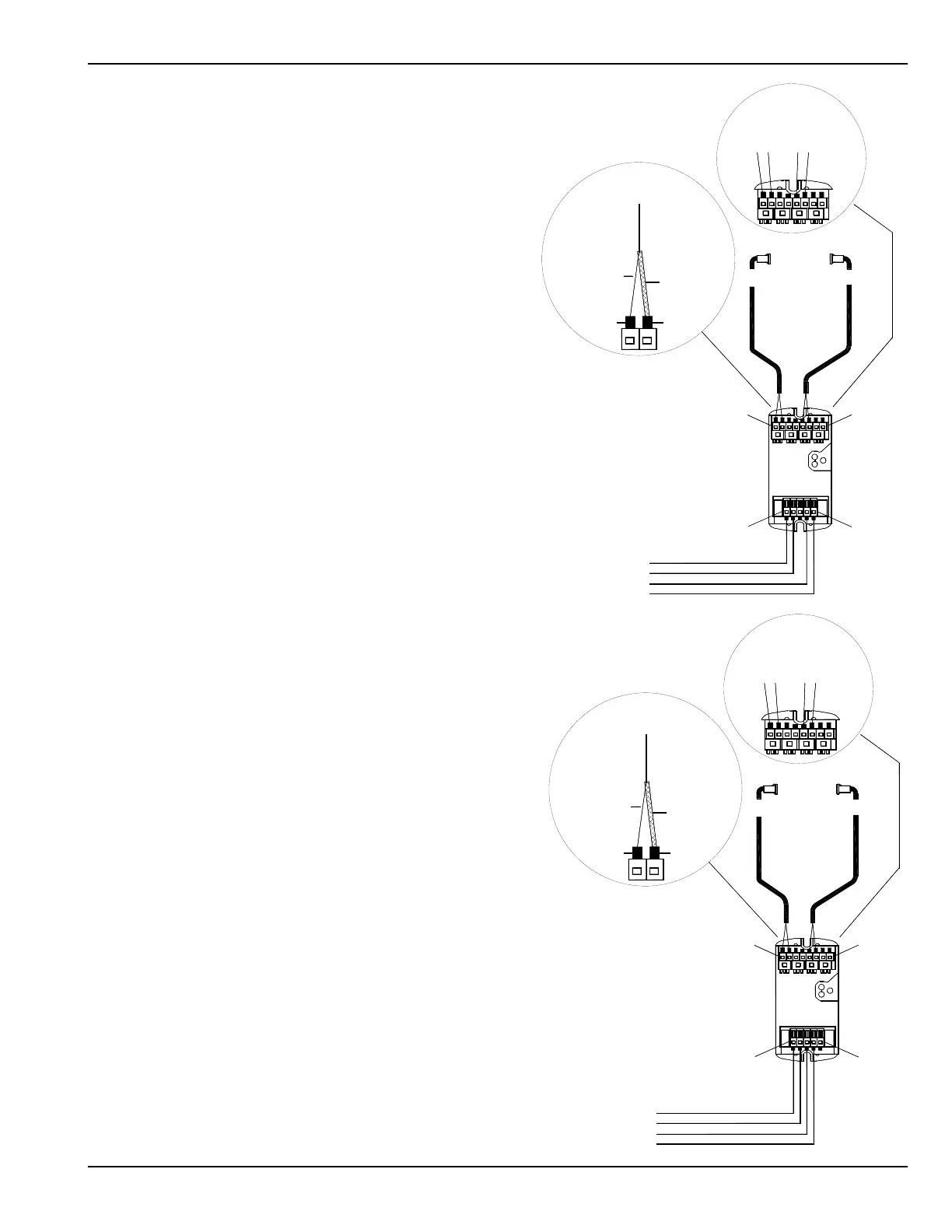
D.2 Infrared Beam Wiring
D.2.1 Wiring Diagram of Optex OS-12C Module for One
Terminal #6
Terminal #1
Terminal #13
Terminal #5
EMTR 1
Gray
RCVR 1
Blue
Optex OS-12C
Controller
Term # & Color
13
12
11 Yellow
10 Gray
9
8
7 Yellow
6 Blue
Yellow
Jacket color
Connect
Each Terminal
the Same
Braided
Shield
Plastic Conductor
Optex Controller
PT. NO. 14-9710-03
Blue
RCVR 1
Gray
EMTR 1
Terminal #5
Terminal #13
Terminal #1
Terminal #6
Power
Power
Signal
Signal
Power
Power
Signal
Signal
Optex Controller
PT. NO. 14-9710-03
Optex OS-12C
Controller
DN 0291
DN 0291
Term # & Color
13
12
11 Yellow
10 Gray
9
8
7 Yellow
6 Blue
Yellow
Jacket color
Connect
Each Terminal
the Same
Braided
Shield
Plastic Conductor
Wiring Diagram for One Holding Beam using Optex
OS-12C Controller on a GT-1175 with U30 control.
Infrared Beam (Activation-Hold Open)
The infrared beam assembly is a factory-installed unit
consisting of an emitter, detector and control box. They
are flush mounted in door frames and/or jamb tubes,
facing each other along the threshold. A pulsed, infrared
light beam is continuously transmitted across the door
opening. Interruption of the beam will switch the White
holding beam input wire to Red (Common). This will
cause the system to re-activate and hold open until the
interruption is cleared.
Wiring Diagram for One Breakout Beam using Optex
OS-12C Controller on a GT-1175 with U30 control.
Infrared Beam (Breakout—Power Interrupt)
The infrared beam assembly is a factory-installed unit
consisting of an emitter, detector and control box. The
emitter and detector are flush mounted in door frames
and/or jamb tubes, facing each other. A pulsed, infrared
light beam is continuously transmitted across the door
opening. Interruption of the beam by breaking out a door
panel will interrupt the Blue (BA) wire power down loop.
This will cause the system to stop operating until the
door panel is repositioned and latched.

 Loading...