Page 4 www.NabcoEntrances.com 04-24-08
U30 Electrical Installation Manual
A.1.5 U30 Power Output Guidelines
When choosing sensors or auxiliary equipment such as modules that will be powered by the U30 control, use the
following rule of thumb: The TOTAL current draw from the U30 for all accessories including sensors and modules must
not exceed 350 mA (0.35 amps) otherwise an auxiliary power supply must be used.
The Nabco power supply module P/N 14-11741 can
be used as a 20 VAC auxiliary power supply provided the TOTAL
power drawn for accessories does not exceed 8 Watts.
NOTE: The U30 and/or the Nabco power supply must not be used to power electric strikes or magnetic locks.
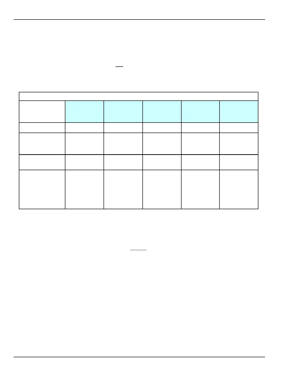
Acusensor 1B
Acuvision
Acumotion A
Optex Beam
Module
CP/RX Radio
Control
Receiver
Part number
14-8902-B
14-10823-01
14-10364-A
14-9710-01
24-11467
Function Infrared Sensor Infrared Sensor
Infrared/
Microwave
Sensor
Module Module
Power source
12 to 24 AC or
DC
12 to 24 AC or
DC
12 to 24VDC
or 24 VAC
12 to 24 AC
or 12 to 30VDC
12 to 24 AC or
DC
Current
consumption
(ea. unit) at
12 VDC
70mA
80mA
160mA
160 mA
290 mA
Current consumption of Various Sensors and Modules
To determine if an auxiliary power supply must be used, simply add up the total current draw of the devices.
Example if a slider is to be fitted with the following devices:
As seen above, this exceeds the total current output of 350 mA of the U30 control and therefore the Optex Beam
Module must be powered separately. This scenario is illustrated in drawing D.1.2 in this manual.
In general the U30 Control supplies power for two sensors. The holding beams are powered from the Nabco power
supply. See wiring diagrams for details.
2 x Acumotion Sensors
=
320 mA
1 x Optex Beam Module
=
160 mA
Total
=
480 mA

 Loading...