Page 5 www.NabcoEntrances.com 04-24-08
U30 Electrical Installation Manual
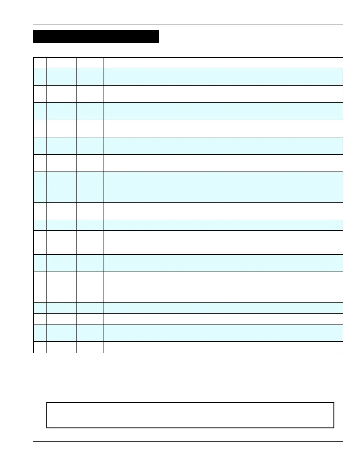
16 Pin Controller Terminal Block Assignments (All wires are identified by color)
No. Symbol Color* Description
1 9DC12V Brown
This output terminal is a sensor power source. The output is 12 VDC with a maximum
capacity of 0.35 amps.
2 7 Red
This output terminal provides common ground for the 12 VDC power and
signal source.
3 61 Black
This terminal is an activation signal input and will open the door based on a signal from
the sensor that is active in one way mode.
4 6B White
This terminal is the holding beam input, it will open or re-open a door when the holding
beam signal is activated.
5 H Green
This terminal is the reduced opening input. It enables reduced door opening when
switched to Red (7).
6 M0 Orange
This terminal is the mode input switch one (SW1). It is used to achieve special functions
(Refer to section C on page 6).
7 M1
Orange/
White
This terminal is the mode input for switch two (SW2). It is used to achieve special func-
tions. If an electric lock is used, the wire will show the lock’s status. (Refer to section C on
page 6)
8 62
Black/
Red
This input terminal receives the signal from the sensor that is switched out in ONE WAY
mode.
9 SQ Yellow This input terminal allows a sequence of signals to open and close the door.
10 BA Blue
This input terminal connects directly to Red (7) during normal operation. When the rocker
switch is turned OFF or if the door is panicked open, it is disconnected from Red. It then
stops door operation.
11 SLS
Green/
White
This terminal is the sidelite protection sensor input. At the fully closed position, this input
will prevent the door from opening.
12 OUT A Gray
This terminal is connected to the Normally Open contact on an internal relay. It is referred
to as the “auxiliary relay output” elsewhere in this manual. It is used as a switch to se-
quence an electric strike, control other doors in an airlock situation or signal a remote
computer on the door operation.
13 OUT B Gray This terminal is connected to the Normally Closed contact on an internal relay.
14 OUT C Violet This terminal is the common for output wire OUT A or OUT B.
15 OUT
Brown/
Yellow
This terminal is connected to an internal transistor with open collector in the Controller.
16 7 Red This terminal provides common ground for the 12 VDC power and signal source.
NOTE: Use a flat-blade screwdriver to remove the terminal connector from the control. Be careful
to ensure all wires are matched to the appropriate terminals. Each terminal is numbered with
corresponding information on the face plate of the control.
* Color1/Color2 denotes a base wiring Color1 with a stripe Color2. For instance Black/Red indicates a Black wire with
a Red stripe.
NOTE: All references to the signals are made in connection with Common (red).
B. Terminal Block Assignments

 Loading...