Do you have a question about the NAD 1700 and is the answer not in the manual?
Technical specifications for the preamplifier stage, including input sensitivity, overload, and S/N ratio.
Specifications for CD, Video, Tape, and EPL inputs, covering impedance, sensitivity, and frequency response.
Specifications for audio outputs, including impedance, maximum level, and infrasonic filter characteristics.
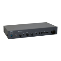
Adjusts the high-frequency response of the audio signal.
Adjusts the low-frequency response of the audio signal.
Provides specific bass boost settings at different frequencies.
Engages a filter to reduce very low-frequency noise.
Detailed performance metrics for FM radio reception, including sensitivity and separation.
Specifies the minimum signal strength for usable AM reception.
Measures AM tuner's ability to reject adjacent channels and images.
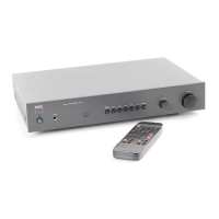
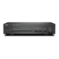
Overall physical size and weight of the NAD 1700 unit.
Essential safety measures for technicians servicing the device.
Guidance on connecting and using oscilloscopes and FM generators for alignment.
Diagram and notes for setting up the detector probe circuit.
List of test instruments required for accurate FM tuning.
Important preparatory steps and considerations before starting FM alignment.
Procedure to set the frequency of the FM local oscillator.
Adjustments for the FM receiver's front-end stages.
Calibration steps for the Intermediate Frequency amplifier circuits.
Fine-tuning the detector circuit for optimal signal recovery.
Procedures to maximize stereo separation and minimize distortion.
Setting thresholds for automatic tuning and stereo switching.
Adjusting the signal strength indicator and muting function.
Adjustments related to the FM noise reduction filters.
Visual guide to component locations on the main PCB.
Visual guide to component locations on the tuner PCB.
Tuning the local oscillator for the AM band.
Adjusting antenna input and IF stages for AM reception.
Setting the signal strength indicator for the AM band.
Ensuring equal audio output levels between left and right channels.
Diagram showing how different circuit boards and components are wired.
Wiring details for the power supply and transformer connections.
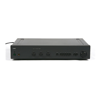
Wiring for antenna connections and various audio/control inputs and outputs.
Detailed layout of the pre-amplifier and power supply circuit board.
Layouts for headphone, LED indicator, and power switch boards.
Schematic representation of audio signal flow for both channels.
Schematic details of tone control and infrasonic filter circuits.
Component placement diagram for the primary tuner circuit board.
Layouts for the FM front-end and rotary sensor modules.
Schematic of the FM receiver's initial signal processing stages.
Schematics for stereo decoding and AM reception circuits.
List of parts used in the FM front-end assembly.
List of components found on the main tuner circuit board.
Component lists for tactile switch and LED indicator boards.
List of components for the main pre-amplifier and power supply board.
Component lists for headphone, power switch, and chassis-mounted items.
Reference numbers for front panel and display components.
Reference numbers for tuner and main circuit board assemblies.
Reference numbers for other PCB assemblies and controls.
| Frequency Response | 20Hz - 20kHz ±0.5dB |
|---|---|
| Power Output | N/A (Preamplifier) |
| Input Impedance | 47kΩ |
| Input Sensitivity | 150 mV |
| Type | Stereo Preamplifier |