Do you have a question about the Nakamichi 482 and is the answer not in the manual?
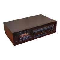
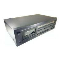
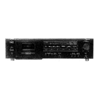
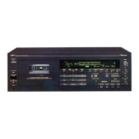
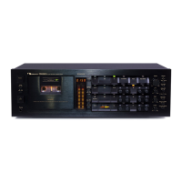
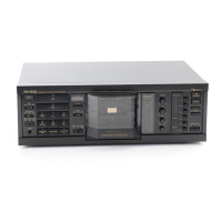
Details Nakamichi 482 control functions shown in the front view.
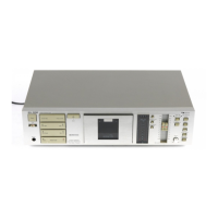
Explains voltage selector on the rear panel for different voltage settings.
Explains the tape travel mechanisms and headblock of Nakamichi 482.
Details the Nakamichi 482 headblock for stabilized tape travel and its components.
Shows sectional view and characteristics of the Direct-Flux Erase Head.
Explains the double capstan system for stable holdback tension and wow/flutter.
Explains the mechanism control cam timing and operation for various modes.
Details the amplifier circuits for playback, record, and bias oscillation.
Details the playback equalizer amplifier circuit and its time constants.
Describes the record equalizer amplifier circuit, calibration, and bias trap.
Explains the bias oscillator circuit for recording bias and erase signal.
Explains mechanism control circuits including buttons, auto shut-off, and signals.
Explains control button operations and interlocks for Nakamichi 482.
Details the auto shut-off function to stop tape at end during playback or record.
Describes the circuit producing +12 V power source from +24 V DC supply.
Explains the power-mute signal generated during power switch ON/OFF.
Details the auto shut-off circuit and timing chart for tape end detection.
Details how mode changes affect Nakamichi 482 operation and memory rewind.
Explains the record control circuit, protection, and unattended recording.
Details the conditions for muting the amplifier circuit based on various signals.
Explains the control motor drive circuit and its relationship to cam position.
Details the reel motor governor circuit for speed control and take-up function.
Procedure for removing the cassette case cover assembly.
Procedure for removing the top cover assembly.
Procedure for removing the bottom cover assembly.
Procedure for removing the front panel assembly.
Procedure for removing the headphone jack assembly.
Procedure for removing the mechanism assembly.
Procedure for removing the meter assembly.
Procedure for removing lamp PCB assemblies.
Procedure for removing the main printed circuit board assembly.
Procedure for removing the control switch holder assembly.
Procedure for removing the switch printed circuit board assembly.
Procedure for removing volume and control switch PCB assemblies.
Procedure for removing rear panel, power transformer, and power switch.
Procedure for removing cassette case and cover plate assemblies.
Procedure for removing the tape counter assembly.
Procedure for removing capstan motor and flywheel assemblies.
Procedure for removing the sub mechanism chassis assembly.
Procedure for removing control and reel motor assemblies.
Procedure for removing the cam control volume.
Procedure for removing reel hub and idler assemblies.
Procedure for removing cam drive gear and control cam.
Procedure for removing the head mount base assembly.
Procedure for removing pressure roller assemblies and erase head.
Procedure for removing playback and record head assemblies.
Details offset and fine adjustment of the control motor driver for cam timing.
Observing reference voltage at the sliding contact of the cam control volume.
Lists typical reference voltages for cam control volume in different modes.
Lists resistors for adjustment and their typical values.
Step-by-step procedures for adjusting mechanism control cam.
Procedure for adjusting tape speed using a frequency counter and test tape.
Procedure for adjusting tilt of record and playback heads using tilt check gauges.
Procedure for adjusting head base stroke using stroke check gauges.
Procedure for adjusting tape guides and erase head stroke.
Procedure for adjusting erase head height and tilt using EH tilt check gauge.
Procedure for adjusting playback/record head height and azimuth alignment.
Procedure for adjusting record head stroke using a mounting gauge.
Procedure for adjusting tape travelling using modified cassette tape.
Procedure for adjusting flywheel holder and thrust screws.
Procedure for adjusting the eject wire.
Lubrication points for replaced parts in the Nakamichi 482.
General instructions for performing electrical adjustments and measurements.
Procedure for adjusting playback frequency response for middle and high frequencies.
Procedure for checking Dolby NR circuit operation and accuracy.
Mounting diagram and parts list for the volume PCB assembly.
Mounting diagram and parts list for the control switch PCB assembly.
Mounting diagram and parts list for the switch PCB assembly.
Mounting diagram and parts list for the control PCB assembly.
Mounting diagram and parts list for the auto shut-off PCB assembly.
Mounting diagram and parts list for the left lamp PCB assembly.
Mounting diagram and parts list for the right lamp PCB assembly.
Mounting diagram and parts list for the main PCB assembly.
Exploded view and parts list for the synthesis mechanism.
Exploded view and parts list for the front panel assembly.
Exploded view and parts list for the synthesis mechanism assembly.
Exploded view and parts list for the meter escutcheon assembly.
Exploded view and parts list for control switch holder assembly.
Exploded view and parts list for headphone jack assembly.
Exploded view and parts list for the mechanism assembly 482.
Exploded view and parts list for the chassis assembly.
Exploded view and parts list for the flywheel holder assembly.
Exploded view and parts list for the sub mechanism chassis assembly.
Exploded view and parts list for the main mechanism chassis assembly.
Exploded view and parts list for the rear panel assembly.
Exploded view and parts list for the reel motor assembly.
Exploded view and parts list for the control motor assembly.
Exploded view and parts list for the head mount base assembly.
Exploded view and parts list for the supply pressure roller assembly.
Exploded view and parts list for the take-up pressure roller assembly.
Exploded view and parts list for head base assembly C.
Exploded view and parts list for cassette case holder L assembly.
Exploded view and parts list for cassette case holder R assembly.
Exploded view and parts list for auto shut-off assembly.
Exploded view and parts list for pneumatic damper assembly.
Exploded view and parts list for P-8L playback head assembly.
Exploded view and parts list for R-8L record head assembly.
Graph showing playback frequency response with different EQ settings.
Graph showing record current frequency response with different EQ settings.
Block diagram illustrating the amplifier section of the Nakamichi 482.
Block diagram showing the mechanism control circuits and their interconnections.
| Brand | Nakamichi |
|---|---|
| Model | 482 |
| Category | Cassette Player |
| Language | English |