Do you have a question about the Nakamichi ZX-7 and is the answer not in the manual?
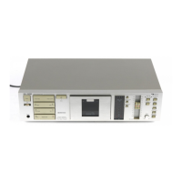
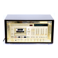
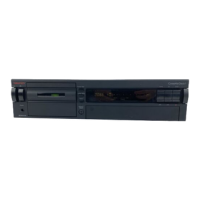
Details the functions of the front and rear panel controls.
Step-by-step instructions for removing the top cover assembly.
Step-by-step instructions for removing the bottom cover assembly.
Instructions for removing the cassette case cover assembly.
Procedures for removing the front panel assembly.
Instructions for removing the main mechanism assembly.
Steps to remove various printed circuit board assemblies.
Procedures for removing record cal, sub chassis, switch/volume, main, and other small PCBs.
Instructions for removing the rear panel and power transformer.
Removing cassette parts, motors, gears, and rollers.
Procedures for removing cam drive gear and head mount base.
Steps to remove erase head, pressure rollers, tape guides, and playback/record heads.
Adjusting the mechanism control cam for proper operation.
Adjusting reel motor speed and record/playback head tilt.
Adjusting head base stroke and erase head stroke/guide height.
Adjusting erase head height/tilt and back tension.
Aligning heads, adjusting azimuth, and record head stroke.
Adjusting tape travel, flywheel, speed, and performing lubrication.
General instructions for performing electrical adjustments and measurements.
Aligning playback head azimuth, calibrating level, and head track alignment.
Adjusting bias oscillation, erase current, record equalizer, bias trap, and record head.
Measuring frequency response, crosstalk, S/N, THD, and wow/flutter.
Adjusting playback and record frequency response curves.
Checking the functionality of the Dolby NR circuits.
Diagrams and parts lists for various small PCB assemblies.
Diagrams and parts lists for control switch and record calibration PCBs.
Diagrams and parts lists for switch and Dolby NR PCBs.
Mounting diagram and parts list for the logic and power PCB.
Diagram and parts list for the main PCB.
Overview of mechanism synthesis and front panel assembly parts.
Parts for chassis, escutcheons, control house, and headphone holder.
Parts for main mechanism, rear panel, flywheel, sub chassis, and main chassis.
Parts for capstan motor, reel motor, control motor, and head mount base.
Parts for pressure rollers, head bases, cassette holders, auto shut-off, and damper.
Parts for playback and record head assemblies.
Graph showing playback frequency response characteristics.
Graph showing record frequency response characteristics.
Block diagram illustrating the amplifier section.
Block diagram illustrating the mechanism control section.
Important notes and precautions for service personnel.
Diagrams of integrated circuits used in the device.
| Type | Cassette Deck |
|---|---|
| Track System | 4-Track, 2-Channel Stereo |
| Motor | DC Servo Motor |
| Heads | 3 (erase, record, playback) |
| Tape Type | Normal, Chrome, Metal |
| Frequency Response | 20 Hz to 20 kHz |
| Total Harmonic Distortion | 0.8% |
| Input | Line In, Microphone In |