StarLink
™
SLE-LTE Commercial Series Alarm Communicators -- Installation Instructions 13
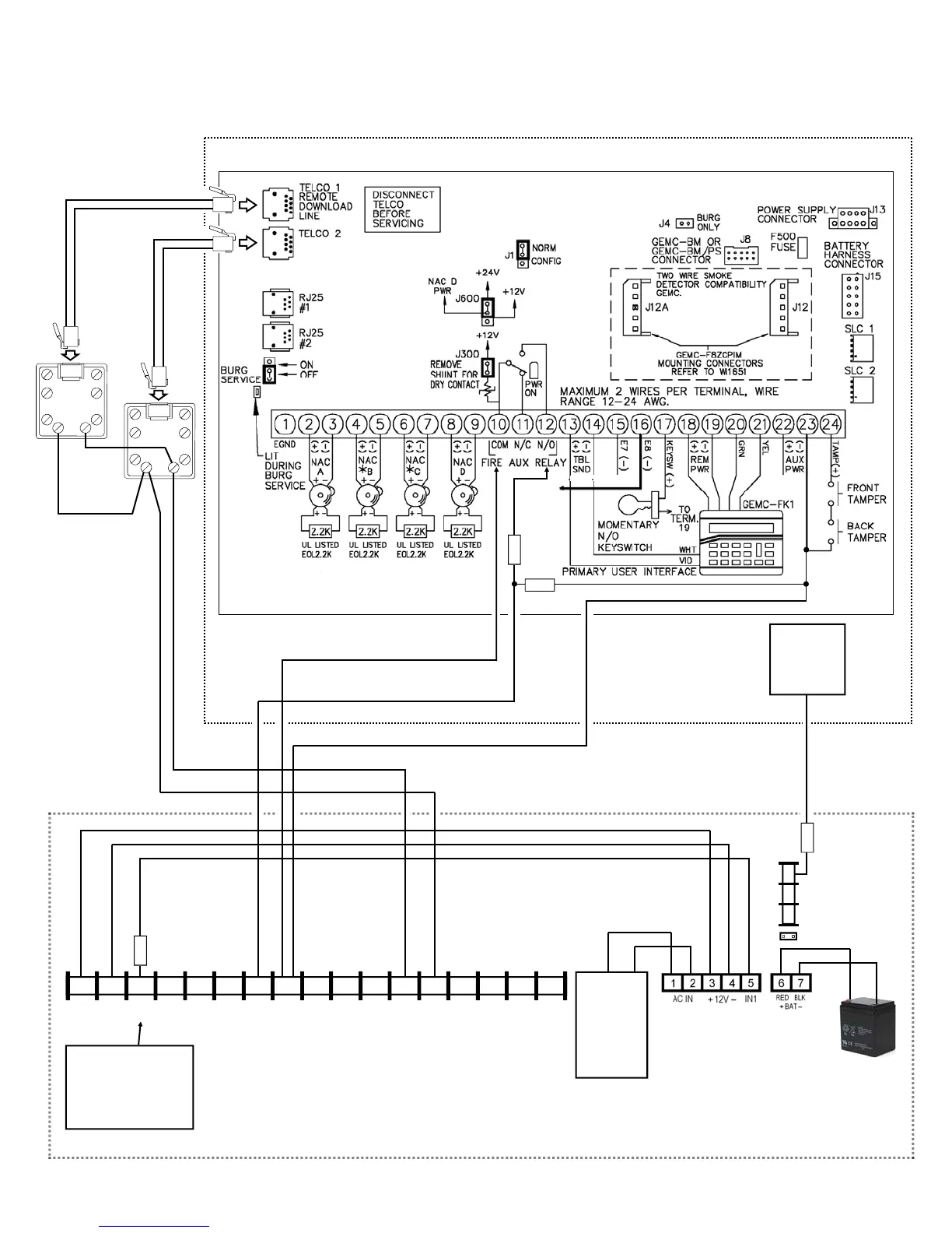
Wiring Diagram for PRIMARY Reporting Configuration
GEMC-32, GEMC-96, GEMC-128 and GEMC-255 Control Panels
(Use when telephone line is NOT available)
RJ31X
RING TIP
GEMC Control
Panel PC Board
10K
SEE WIRING
DIAGRAM
AND WI FOR
ADDITIONAL
INFORMATION
RJ31X
RING TIP
*Refer to section "SUPPLYING POWER".
6 7 8 15 14 13 12 11 9 10 2* 3 4 5 1*
+V
(–)
PGM1 PGM2 PGM3 IN1 IN2 GND IN3 RING TIP
17 16
RTS
(R)
PANEL
TX (B)
PANEL
RX (G)
CTS
Y
StarLink Radio Terminals
PANEL
RING (+)
PANEL
TIP (–)
(STARLINK RADIO HOUSING)
Either the
TRF12/T123
(16.5V / 20VA)
transformer
or the chassis-
mounted
16.5VAC /
20VA
transformer
StarLink
BATTERY
(+)
RED
(–)
BLACK
Power Supply (SLE-ULPS-R)
(optional)
2.2K
8 9 10
N/C
COM
N/O
J2
2.2K
ZONE (+)
DEDICATED
TO SUPER-
VISION
(CONTROL PANEL HOUSING)
SLE-LTEV-CB-TF PC Board: All con-
nections are power limited except AC
Mains, Telco and battery terminals. Ter-
minals 14-17: No connections permitted.
TELCO TROUBLE OUTPUT
COM
10K
Wire to dedicated zone
on the control panel for
Supervision when the
Power Supply board
(SLE-ULPS-R) is not
used.
Note: Connect IN2
to a panel output used
for identifying Telco
line cut (this is the
DACT interconnect
wiring to the radio).