10 StarLink
™
Connect SLECDMA-CB Series Alarm Communicators -- Installation Instructions
Using StarLink Connect Software with
DSC Control Panels
The Napco StarLink Connect software is compatible with the
DSC DLS Programming Software. See www.dsc.com for
more information regarding DSC control panel compatibility
with their DLS software. Before proceeding, the StarLink
Connect SLE radio must be wired to the DSC control panel as
described earlier in this manual.
1. Before connecting each time to the DLS Programming
Software, launch the Napco StarLink Connect software
by pressing "Alt + S" on
the keyboard. In the
popup that appears, click
the DLS tab and type the
StarLink radio Device ID
(printed on the radio PCB
sticker) and click OK.
Note: Always verify the
radio is a "StarLink
Connect" radio with the correct panel type before
entering "ready to connect" mode (click Info to view radio
data). In addition, the PC-Security Code prompt will
appear if a Code was used (the app will remember the
last Code used until you exit the app from the System
Tray).
2. When the Napco StarLink Connect icon in the
System Tray turns green with a black "D" in the
center (shown at right), the Napco StarLink
Connect software is ready to connect with the
DSC DLS Programming Software.
3. Launch the DSC DLS Programming Software and log in
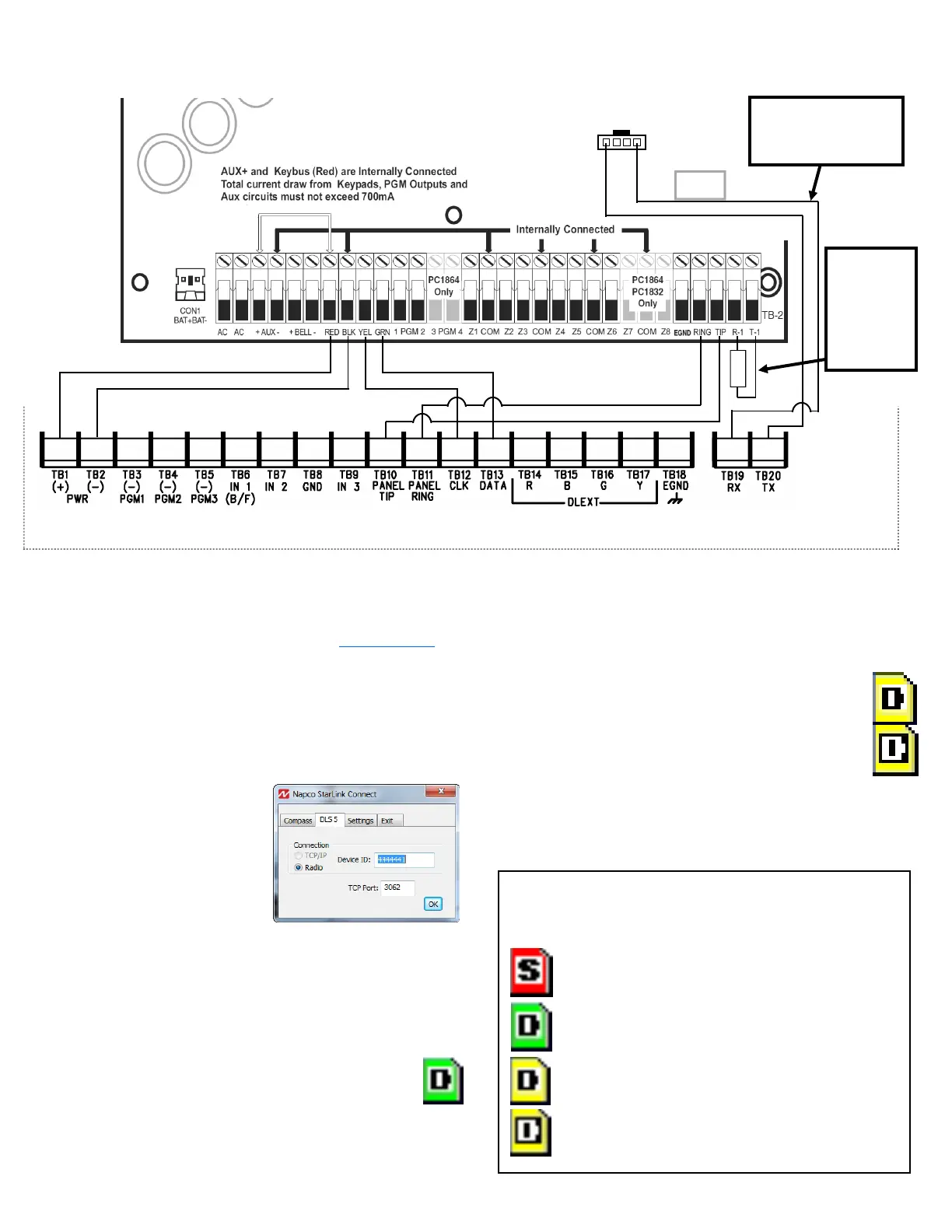
DSC Control Panel Connections
normally. When connected to the DSC DLS
Programming Software, the Napco StarLink Connect
icon in the System Tray turns yellow. Upload, download
and/or program the DSC control panel as usual.
4. To indicate real-time communication activity from
the DSC DLS Programming Software, through
the Napco StarLink Connect software to the
DSC control panel, the "D" in the center of the
yellow StarLink icon will toggle between "black
on white" and "white on black".
5. Upon disconnection, the yellow StarLink icon turns back
to green and waits for another DSC DLS Programming
Software connection. The last Radio ID used will be
retained in memory (RAM) for convenient reconnection.
The Napco StarLink Connect software state changes
are reflected in the appearance of its System Tray
icons:
Red Icon: "Stopped" (initial state)
Green Icon: "Listening for DLS
Programming Software outgoing connection"
Yellow Icons: "Connected with DLS
Programming Software". During data
transfer, yellow icon will toggle between
"black on white" and "white on black" to
indicate data transfer activity.
(DSC1864)
(STARLINK RADIO HOUSING)
StarLink Radio Terminals
10K EOLR
PC LINK
RED
BLK
RED
BLK
10K EOLR
required
when TIP/
RING Wiring
Fault Report
is enabled
Use Cable labeled
"DSC PC-LINK
HARNESS" (part W1154)
 Loading...