StarLink™ Connect SLECDMA-CB Series Alarm Communicators -- Installation Instructions 7
(Commercial Fire and Commercial Burglary)
SLECDMA-CB-C & SLECDMA-CB-TF-C
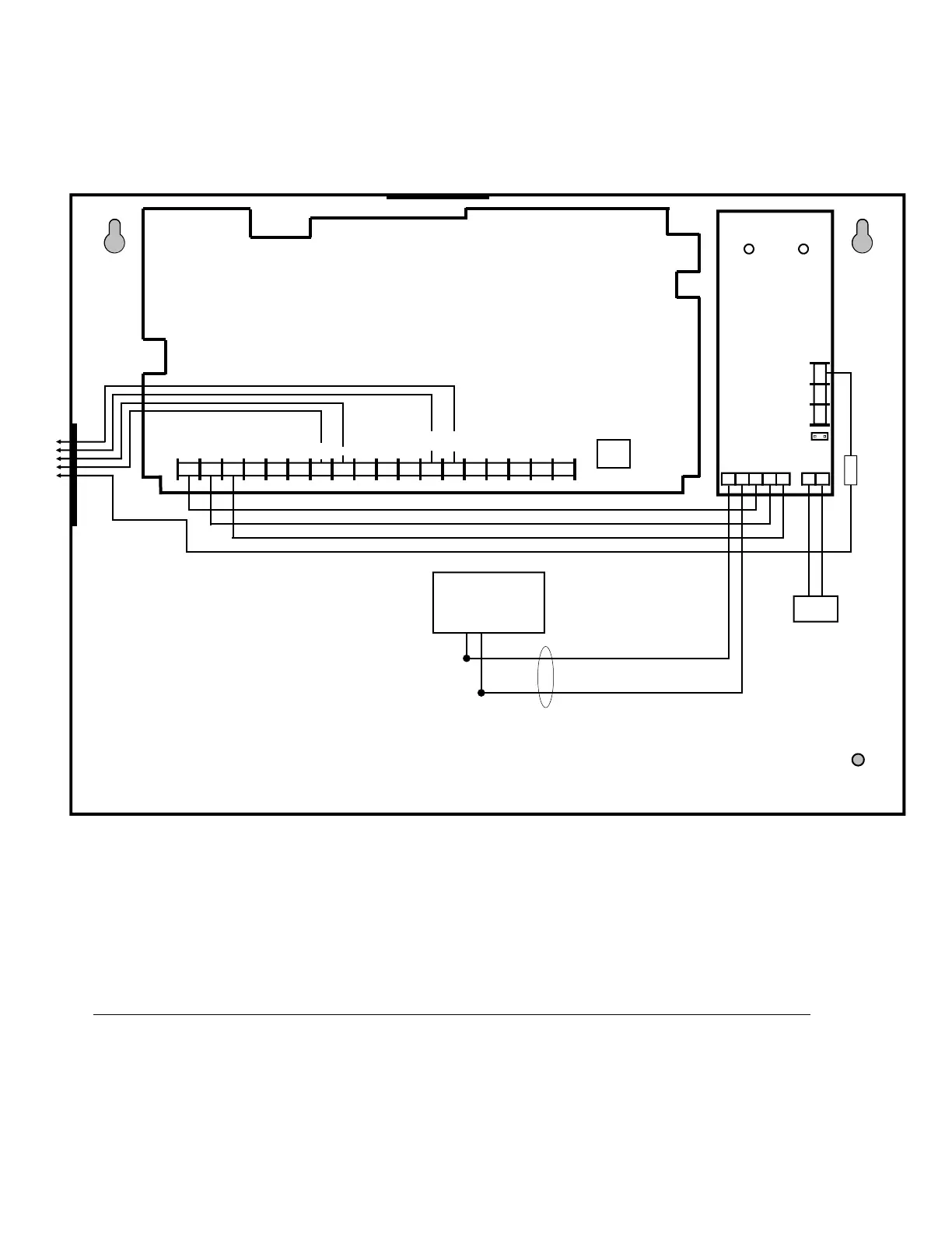
Wiring Diagram
SLECDMA-CB-C & SLECDMA-CB-TF-C
PC Board
All connections are power limited except Telco
and battery terminals
Power Supply
(SLE-ULPS-R)
6 7 8 15 14 13 12 11 9 10 2* 3 4 5 1*
+12V
(–)
PGM1 PGM2 PGM3 IN3 RING TIP
17 16
RTS
(R)
PANEL
TX (B)
PANEL
RX (G)
CTS
Y
Yellow
Trouble
LED
Green AC
ON LED
+ BAT –
RED BLK
6 7 2 3 4 5 1
8 9 10
N/C
COM
N/O
Black (‒)
Red (+)
Battery
PANEL
RING
PANEL
TIP
GND
16.5VAC
Class 2
*Notes:
Connect the StarLink radio to the control panel output for Telco Trouble (this is the DACT interconnect wiring to
the radio). Remember to program the StarLink communicator module to report this IN2 Telco Trouble and for
line cut (EOLR) to the central station. In addition, always add an EOLR at the control panel Telco Trouble
Output (Fire Aux Relay for the GEMC control panels).
Use EOLR value as specified by the control panel installation instructions.
IN1 not supervised. IN2 and IN3 can be supervised.
Keep all non-power limited wiring separate from all power-limited wiring inside the housing by 1/4".
Remove shunt J2 to isolate relay common from ground (i.e. jumper on = wet (circuit common); off = dry
contact). When wet, configuration is used; the power should be derived from the alarm control panel.
StarLink module must be configured to trigger PGM1 on any trouble.
PGM1 of the StarLink module must be wired to the trouble input (terminal 5) of the power supply.
The Power Supply Trouble Output must be wired to a control panel zone dedicated to a radio trouble; see
control panel programming instructions and program to Report Alarm / Alarm Restore / Trouble / Trouble
Restore.
IN1
+ 12V –
AC IN
Note: Maintain
minimum 1/4"
separation of
battery leads from
all other wiring.
EOLR*
IN1
J2
Remove shunt J2 to isolate relay
common from ground (i.e. jump-
er on = wet; off = dry contact)
Terminals 14-17: No connections permitted.
Relay con-
tacts rated
max 30VDC,
0.5A
12VDC
output is
power limited
IN2*
Note: Connect IN2 to a
panel output used for
identifying Telco line cut (this
is the DACT interconnect
wiring to the radio).
TRF12/T123
16.5V / 20VA
Transformer
EARTH
GND
18
ETHERNET
(To control panel*)
 Loading...