8 StarLink
™
Connect SLECDMA-CB Series Alarm Communicators -- Installation Instructions
(STARLINK RADIO HOUSING)
StarLink Radio Terminals
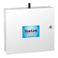
Wiring Diagram for PRIMARY Reporting Configuration
GEM-P816 / GEM-P1632 / GEM-P1664 Control Panels
13 14 15 16 17 18 19 20 21 22 26 27 28 29 23 24 25
~ ~
(un-polarized)
*Refer to section
"SUPPLYING
POWER".
TIP RING TIP RING
TELCO PHONE
~
2.2K
ZONE (+)
DEDICATED TO GPRS
SUPERVISION
~ ~
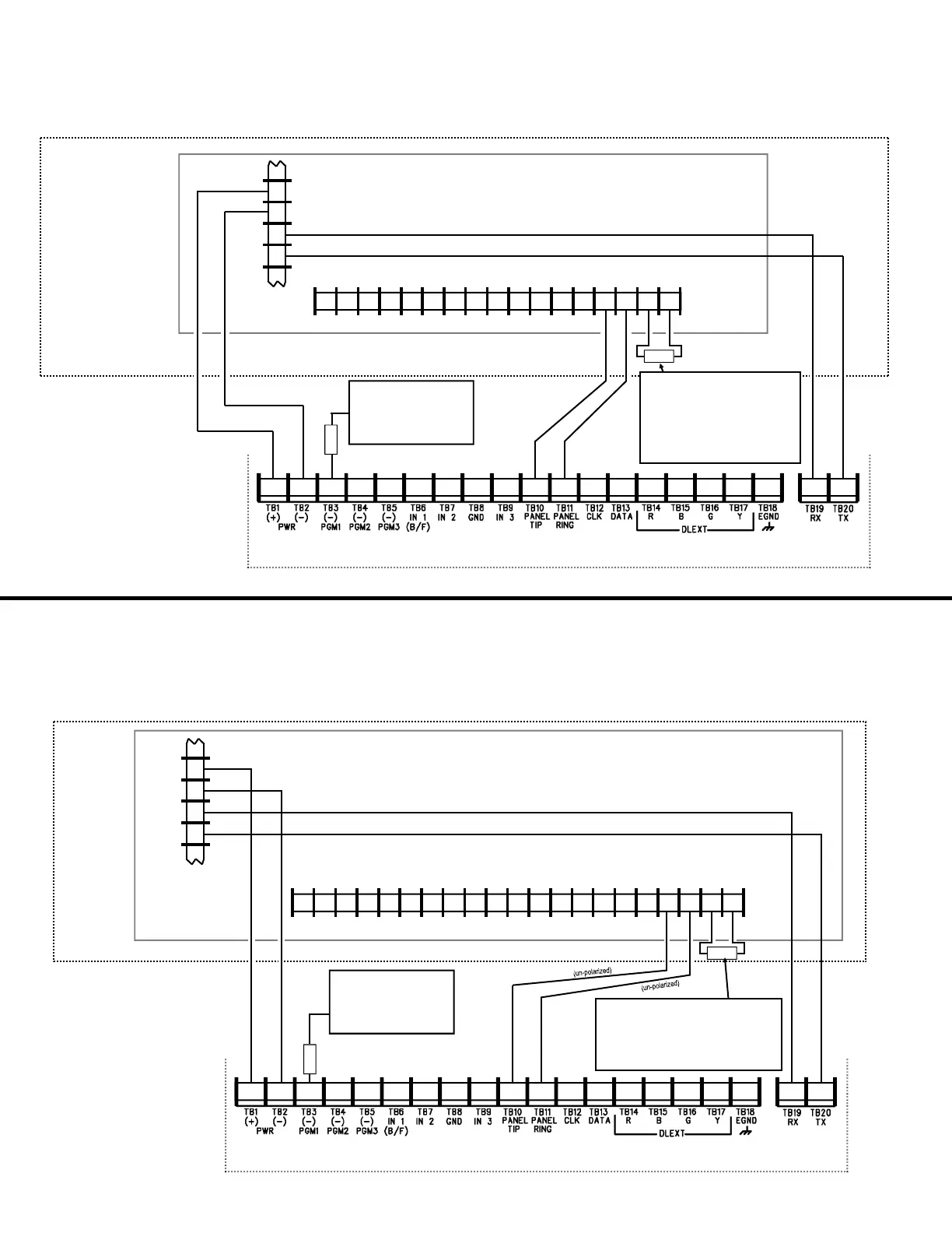
Wiring Diagram for PRIMARY Reporting Configuration
GEM-X255 / GEM-P9600 / GEM-P3200 Control Panels
(CONTROL PANEL HOUSING)
13 14 15 16 17 18 19 20 21 22 26 27 28 29 23 24 25 33 30 31 32
Control Panel PC Board
~ ~
*Refer to section
"SUPPLYING
POWER".
TIP RING TIP RING
TEL LINE PHONE
2.2K
(CONTROL PANEL HOUSING)
(STARLINK RADIO HOUSING)
StarLink Radio Terminals
9
10
11
REMOTE
BUS
BLK
GRN
12
YEL
RED
Control Panel PC Board
~
(un-polarized) (un-polarized)
9
10
11
REMOTE
BUS
BLK
GRN
12
YEL
RED
(‒)
TX
RX
(+)
(un-polarized)
ZONE (+)
DEDICATED TO GPRS
SUPERVISION
10K
10K EOLR required when TIP/RING
Wiring Fault Report is enabled in
the Napco "NOC". For optional
local line fault annunciation, enable
the Telco Line Cut Monitor feature
in the control panel programming.
10K
10K EOLR required when TIP/RING Wiring
Fault Report is enabled in the Napco "NOC".
For optional local line fault annunciation,
enable the Telco Line Cut Monitor feature in
the control panel programming.
 Loading...