2 StarLink
™
Connect SLECDMA-CB Series Alarm Communicators -- Installation Instructions
Electrical Ratings for IN 2 and IN 3:
Maximum Loop Voltage: 15VDC max.
Maximum Loop Current: 1.2mA
End of Line Resistor (EOLR) Value: 10K
Electrical Ratings for 3 PGM Outputs:
Open Collector Outputs: Maximum Voltage 3V when
active; 15V maximum when not active
Maximum PGM Sink Current: 50mA (up to 15VDC)
Physical (W x H x D)
Metal Housing: 11½ x 9½ x 3½" (29.2 x 24.1 x 8.9cm)
Mounting: Metal housing includes two keyhole slots for
wall mounting (see measurements on page 15)
Environmental
Operating Temperature: 0°C - 49°C (32°F - 120°F)
Humidity: Maximum 93% Non-Condensing
Indoor / dry location use only
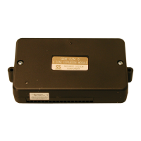
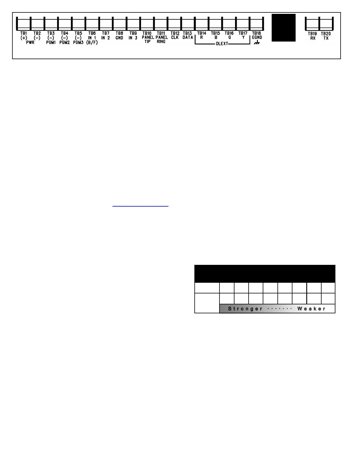
TERMINAL DESCRIPTIONS
Configure all inputs and outputs using the Management
Center (the Napco "NOC" located at http://NapcoNoc2.com).
Located at the bottom of the StarLink radio PC board, the 20
terminals are described as follows:
TB1: PWR (+) +10 - 15VDC.
Do NOT connect to FWR power.
TB2: PWR (–)
TB3: PGM1 (–): Open collector output. PGM1 is nor-
mally on (active low). When it is triggered (for exam-
ple, a trouble is detected) it becomes open collector/
high. To have a zone dedicated to an StarLink radio
trouble, insert one side of the end of line resistor into
this PGM1 terminal, and wire the other side of the
resistor to the positive terminal of the zone.
TB4: PGM2 (–): Open collector output. This output is
normally open collector / high. When a report fails to
communicate anywhere in the communications path,
the output is active low.
TB5: PGM3 (–): Open collector output. This output is
normally open collector / high. Use the Napco "NOC"
to configure options for PGM activation.
TB6: IN 1: Active high input for wiring to the control
panel bell output. When this input detects a pulsing
temporal 3 high, it sends a Fire alarm; a pulsing tem-
poral 4 (CO Alarm), a CO alarm is sent. For this in-
put to report to a central station, the StarLink radio
must be configured with the central station telephone
number and correct reporting formats and codes.
TB7: IN 2: See TB9, below.
TB8: GND: Common ground terminal.
TB9: IN 3: Both terminals IN 2 and IN 3 default to 'User
Defined'; no end-of-line resistor supervision required.
Wire the common ground terminal GND (terminal
TB8) to the relay common. When used as arm/
disarm status input, a low indicates "armed" and a
high indicates "disarmed". For these inputs to report
to a central station, the radio must be configured with
the central station telephone number and correct re-
porting formats and codes.
TB10: PANEL TIP: See wiring diagram(s).
TB11: PANEL RING: See wiring diagram(s).
TB12: CLK: See wiring diagram(s).
TB13: DATA: See wiring diagram(s).
TB14: R: Red wire. See TB17.
TB15: B: Blue wire. See TB17.
TB16: G: Green wire. See TB17.
TB17: Y: Yellow wire. Do NOT connect if using the SLE
-DLCBL Download Cable.
TB18: EGND: Earth ground (optional)
TB19: RX: See wiring diagram(s).
TB20: TX: See wiring diagram(s).
LED DESCRIPTIONS
The PC board contains several LEDs, as follows:
GREEN RF SIGNAL STRENGTH LED
Labeled "D3", this LED is located at the lower right corner
of the PC board (see image).
Every 30 seconds, the StarLink radio receiver section
turns on and listens to the cell tower. Depending on the
signal strength detected, it will blink the Signal Strength
LED from 1 to 8 times, providing a signal strength indicator
that is updated constantly and is always displayed. Refer
to the Coverage Table:
Green LED Operation
Signal strength (as received by the radio) is displayed by
this LED blinking 1 to 8 times at a constant rate (with a
short delay between blink cycles). Acceptable power level
is greater than or equal to -91dBm (minimum 4 blinks at
the mounting location).
YELLOW OPERATIONAL STATUS LED (Radio)
Labeled "D4", this yellow LED is located at the bottom right
of the PC board. Operation is as follows:
Normal Standby Condition:
Blinks on momentarily every 10 seconds: Unit is in
standby waiting for an alarm to report.
Processing Alarm Conditions:
When processing an alarm, this yellow LED will blink
GREEN RF SIGNAL STRENGTH LED
RADIO RECEIVER COVERAGE TABLE
LED Blinks 8 7 6 5 4 3 2 1
-55 -65 -75 -85 -91 -95 -99 -105
Power
(dBm)
ETHERNET
 Loading...