StarLink™ Connect SLECDMA-CB Series Alarm Communicators -- Installation Instructions 1
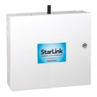
SLECDMA-CB-TF-C - Commercial / Residential Burglary
and Residential Fire Network Compatible CDMA alarm
capture radio communicator in white metal housing. In-
cludes SLE-ULPS-R power supply and TRF12/T123
plug-in 16.5V / 20VA transformer.
ADDITIONAL COMPONENTS
In addition to the models listed above, the
following sub-assemblies are available:
SLE-WIFI-MODULE - Allows your StarLink
™
device to connect to the Internet by means of a wireless
(Wi-Fi) link, eliminating a wired Ethernet cable connec-
tion.
SLE-DLCBL - Download Cable, 6 feet.
SLE-ANTEXT30 - Extended antenna with 30 feet of cable.
SLE-ANTEXT50 - Extended antenna with 50 feet of cable.
SLE-ANTEXT75 - Extended antenna with 75 feet of cable.
(Any suitable external cellular antenna is permitted by
UL). Always follow the manufacturer's installation in-
structions. Note: Antennas are not Listed by UL. For
3/4G radios where an External Antenna needs to be
installed outside of the room in which the radio is in-
stalled (maximum 30 meters (98 feet) in Residential ap-
plications), please use RF Transmitter Board
9GPS5320EXAPSLD available from our Customer Ser-
vice Department, if not provided. The
9GPS5320EXAPSLD is identified by "two red dots" lo-
cated on the lower right corner of the board. See
WI2222 included with the 9GPS5320EXAPSLD for the
simple installation procedure.
SPECIFICATIONS
The following specifications apply to all StarLink radio mod-
els in these installation instructions unless otherwise stated:
Electrical Ratings for +12V (both models powered by the
control panel)
Input Voltage: 10-15VDC (power-limited output from con-
trol panel). Do NOT connect to full-wave rectified (FWR)
power.
Input Current:
SLECDMA-CB-C standby current: 100mA (110mA
with telco EOLR)
SLECDMA-CB-TF-C standby current: 100mA
(110mA with telco EOLR)
Transmission current (all models): 200mA max.
Electrical Ratings for the IN 1 Burg/Fire Input:
Input Voltage: 9-15VDC.
Maximum Input Current: Up to 2mA from control panel
supply circuit
WI2247ALF 8/18
333 Bayview Avenue Amityville, New York 11701
For Sales and Repairs, (800) 645-9445
For Technical Service, (800) 645-9440 or visit us at
http://tech.napcosecurity.com/
(Note: Technical Service is for security professionals only)
Publicly traded on NASDAQ Symbol: NSSC
© NAPCO 2018
OVERVIEW
The StarLink
™
Connect models SLECDMA-CB-C and
SLECDMA-CB-TF-C are multi-function Commercial / Resi-
dential Burglary and Residential Fire alarm radio communi-
cators and supervised system interface modules. They pro-
vide several options to the user:
1. A monitoring path to a central station through a digital
CDMA radio and optionally through a TCP/IP network to
the Internet using a hardwired or optional Wi-Fi connec-
tion;
2. Notification alerts of alarm system changes to a mobile
device. Notifications use iBridge Messenger SMS text
messaging and/or emails to inform the user and/or deal-
er of system state changes. For this release, these noti-
fications are enabled in the iBridge Connected Home
Services website at http://ibridge.napconoc2.com;
3. Both radio models are compatible with most 12VDC
alarm control panels, including Honeywell and DSC
(always adhere to the documentation provided by the
control panel manufacturer). Residing in the Windows
System Tray, the StarLink Connect application allows
you to use your customary control panel communication
software for remote programming and communication:
DSC DLS
Honeywell Compass
®
NAPCO control panels are programmed in the tradition-
al way using PCD-Windows Quickloader software.
StarLink Connect is available on the enclosed CD.
If required, mount the unit to a single-, dual-, or three-gang
electrical box and route the wires through the back knock-
out(s), or as specified by local codes. See WI2140 for pro-
gramming instructions (all manuals are available for
download at http://tech.napcosecurity.com/).
StarLink SLE Series radios use proprietary data-capture
technology that captures the alarm report from the control
panel and transmits the alarm signals to the SLE Control
Center (the Napco "NOC"); the alarm signals are then for-
warded to ANY central station via Contact ID or Sur-Gard
System II or Sur-Gard System V central station receivers via
TCP/IP using standard line security. The SLE Control Cen-
ter reports a trouble signal in the event that the network does
not receive the expected supervision signal from the wire-
less communicator. In addition, both StarLink radio models
can be powered directly from the control panel.
The StarLink radio model names are as follows:
SLECDMA-CB-C - Commercial / Residential Burglary and
Residential Fire Network Compatible CDMA alarm cap-
ture radio communicator in white metal housing. Pow-
ered directly from control panel (no power supply, no
transformer).
StarLink
™
Connect Series
SLECDMA-CB-C & SLECDMA-CB-TF-C
Multi-Function Alarm Communicators
INSTALLATION INSTRUCTIONS