StarLink™ Connect SLECDMA-CB Series Alarm Communicators -- Installation Instructions 3
variably during each part of the process (dialing, hand-
shaking, data transmission, etc.).
This yellow LED will light when communicating with the
phone app and when notifications are transmitted.
RED TROUBLE LED
Labeled "D5", this LED is located at the bottom right of the
PC board. Operation is as follows:
1 Blink: Low Aux Power input voltage
2 Blinks: Battery trouble
3 Blinks: Alarm report Failed to Communicate (will
restore only when both paths are operational)
4 Blinks: RF trouble (antenna connection or cellular
registration)
5 Blinks: Radio poll or check-in failure (radio only).
The unit must only fail on one path to trigger the trouble,
but for the trouble to clear, unit requires both IP and ra-
dio polling / checkins to be operational.
6 Blinks: Unit disabled (reporting or control panel
downloading not allowed)
7 Blinks: Unit was shutdown and has no functionali-
ty; requires a restart (full power down and full power up
sequence) to restore operation.
RED DIAGNOSTIC LED
Labeled "D7", this LED is located in the middle of the PC
board. One blink indicates a weak or non-existent signal
from the network (green LED is off). If this red LED is
blinking in any other manner, please contact technical sup-
port.
NETWORK CONNECTION LEDs
Labeled "DS14" (green), "DS15" (yellow) and
"DS16" (red), these LEDs are located at the bottom
right of the PC board.
The green LED labeled "DS14" describes the IP network
connection type or the connection quality, as follows:
When DS14 is off = No network cable detected
When DS14 is flashing rapidly = No IP connection
(occurs just after power on while trying to obtain an IP
address; therefore has priority over any other green
flashing LEDs)
When DS14 is flashing slowly = Normal operation:
1 Slow Blink: Static IP Address (as programed by
the NOC)
2 Slow Blinks: DHCP (default)
3 Slow Blinks: Auto IP (if unable to acquire DHCP
address, after 5 minutes radio will convert to Auto IP.
The Yellow LED labeled "DS15" describes the status of
the IP network.
When DS15 is off = No power
When DS15 is flashing rapidly = Push button on Wi-Fi
module is being pressed
When DS15 is flashing steady with 1 quick blink off eve-
ry 2 seconds = Reporting signal to NOC
When DS15 is flashing steady with 2 quick blinks off
every 2 seconds = Downloading to control panel or the
module
When DS15 is flashing slowly:
1 Slow Blink: Ethernet available (must detect that
the CAT5 cable is connected and must be connected
to the Internet via customer router, etc.)
2 Slow Blinks: Wi-Fi Station Mode
3 Slow Blinks: Wi-Fi APN Mode (Access Point)
The red LED labeled "DS16" describes the IP network
troubles.
When DS16 is off = No network troubles detected
When DS16 is flashing rapidly = No IP connection
(occurs just after power up while the radio tries to obtain
a DHCP IP address
When DS16 is flashing slowly:
1 Slow Blink: No network cable detected
2 Slow Blinks: No network cable access to the
Internet (mutually exclusive with "1 Blink"). If the radio
is configured for only an Ethernet connection (no Wi-
Fi) and the Ethernet cable is connected but the router
is non-functional, the radio will detect the loss of ac-
cess to the Internet within a programmable amount of
seconds. The default of 500 seconds (8-1/3 minutes)
is intended to display a trouble to the installer sooner
in case the account is set for 1-hour, 24-hour or 7-day
Supervisory Failure
3 Slow Blinks: Ethernet failed to communicate
4 Slow Blinks: Ethernet poll / check-in failure
5 Slow Blinks: Wi-Fi enabled but the SLE-WIFI-
MODULE is not detected
6 Slow Blinks: = No Wi-Fi access to the Internet.
May occur when the Wi-Fi and the network cable each
access the Internet via separate means (for example
two different routers). Note: This indication may be
combined with the "2 Blinks" indication if both the Wi-
Fi and network cable use the same ISP.
7 Slow Blinks: Wi-Fi failed to communicate
8 Slow Blinks: Wi-Fi poll / checkin fail
9 Slow Blinks: Wi-Fi serial data error or no serial
data response
10 Slow Blinks: Wi-Fi Security / Authentication failed
OTHER LEDs
Labeled "D607" (green) and "D606" (red), these LEDs indi-
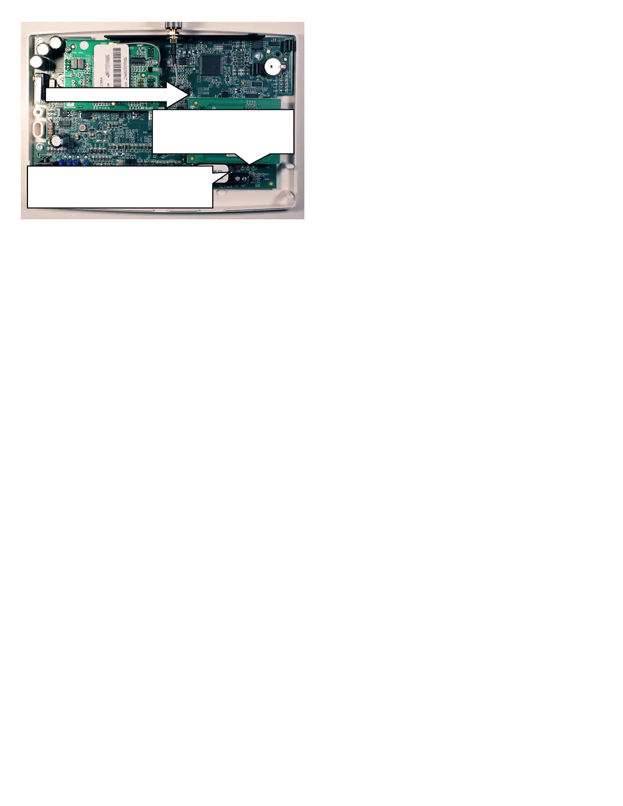
LED LOCATIONS
D4: YELLOW OPERATIONAL STATUS
D3: GREEN RF SIGNAL STRENGTH
D5: RED TROUBLE
DS14: GREEN IP NETWORK TYPE OR QUALITY
DS15 YELLOW IP NETWORK STATE
DS16 RED IP NETWORK TROUBLES
DL: RED DIAGNOSTIC LED
 Loading...