12 StarLink
™
SLE Commercial LTEVI & LTEAI Series Dual-Path Alarm Communicators -- Installation Instructions
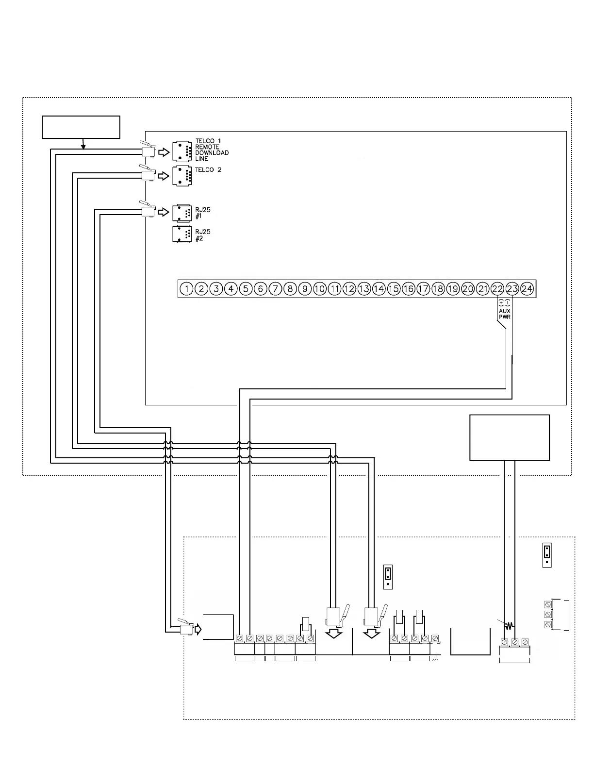
(STARLINK RADIO HOUSING)
StarLink Radio Terminals
LOCAL
DOWNLOAD
TELCO
SECONDARY
TELCO
PRIMARY
ETHERNET
1
(+)
2
(‒)
POWER
PGM3
IN1 IN2 IN3
3
(‒)
4
(+)
5
(+)
6
(‒)
8
(‒)
7
(+)
9
(+)
10
(‒)
12
(‒)
11
(+)
13
EGND
19
N/O
21
N/C
20
C
IN4 IN5
OUT1
22
N/C
24
N/O
23
C
OUT2
Wiring Diagram for GEMC-32, GEMC-96,
GEMC-128 and GEMC-255 Control Panels
(CONTROL PANEL HOUSING)
**
GEMC Control Panel
PC Board
Refer to section "SUPPLYING POWER".
*Not required if JP2 shunt is removed and FACP
monitors TELCO 2.
**Program only TELCO 1 supervision.
Note: Connect IN2 to a panel output
used for identifying Telco line cut (this is
the DACT interconnect wiring to the radio).
PC Board: All connections are power limited except AC Mains and battery terminals.
Or use a
12V/24V UL
Listed
monitored
power supply
10kΩ
10kΩ
10kΩ
EOLR
Requires all 8 wires in
the RJ-45 cable
JP1
Shunt JP1
on top 2 pins
(Optional, for remote
communication)
JP2
Remove JP2 to
enable TELCO2
trouble on
Communicator trouble
To Panel Zone
Dedicated to Radio
Trouble
*
 Loading...