W415-0702 / B / 04.04.12
30
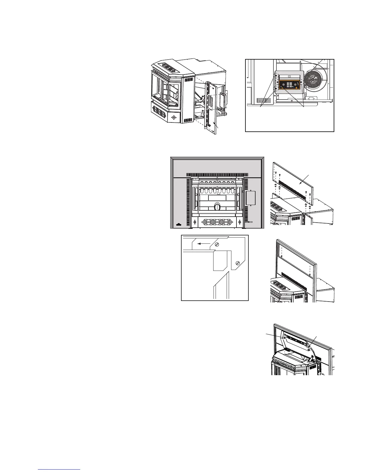
6.2 FLASHING INSTALLATION
A. Secure the right fl ashing to the
right side of the appliance using
two of the #8 x 1/2" screws.
B. Remove the two control panel
securing screws, discard the
screws and shipping bracket.
C. Secure the control panel to the
right fl ashing using the two #8
x 3/8" screws. Secure the left
fl ashing with the remaining #8 x
1/2" screws.
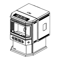
D. Align the holes in the top of the
right and left fl ashing with those
on the bottom lip of the Top
Flashing and secure from the
rear using the four #8-32 x 3/8"
screws, washers and nuts.
E. The three pieces of trim are
assembled in the same manner
as a picture frame. Place the
corner brackets (with screw
loosened) into the trim sections.
Tighten the screw spreading
the two pieces apart. Attach the
adjoining section. Repeat with
the opposite side. Tighten all
screws fi rmly.
F. Slide the assembled trim down
over the fl ashing.
G. Affi x the logo to the bottom left
hand corner of the left fl ashing.
L
O
W
H
I
G
H
1
2
3
4
5
CONTROL
PANEL
RIGHT
FLASHING
PUSH TO START / POUSSEE POUR COMMENCER
W385-0355
5
3
1
2
4
OPTIMUM
1
3
5
4
2
1
3
5
4
2
SHIPPING
BRACKET
SECURING
SCREWS
CONTROL
PANEL
SECURING
SCREWS
TOP
FLASHING
TRIM
ASSEMBLY
TRIM
UNDERSIDE
CORNER
BRACKET
SET SCREW
SET
SCREW
6.3 TRIVET INSTALLATION
The trivet for the insert is attached by
two set screws on the inside of the hop-
per lid