4-14 | ni.com
Chapter 4 Analog Input
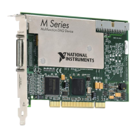
Figure 4-4. Differential Connections for Floating Signal Sources
without Bias Resistors
However, for larger source impedances, this connection leaves the DIFF signal path significantly
off balance. Noise that couples electrostatically onto the positive line does not couple onto the
negative line because it is connected to ground. This noise appears as a differential mode signal
instead of a common-mode signal, and thus appears in your data. In this case, instead of directly
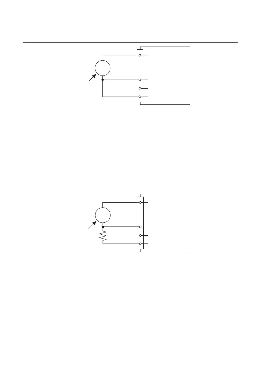
connecting the negative line to AI GND, connect the negative line to AI GND through a resistor
that is about 100 times the equivalent source impedance. The resistor puts the signal path nearly
in balance, so that about the same amount of noise couples onto both connections, yielding better
rejection of electrostatically coupled noise. This configuration does not load down the source
(other than the very high input impedance of the NI-PGIA).
Figure 4-5. Differential Connections for Floating Signal Sources
with Single Bias Resistor
–
+
Inpedance
<100 Ω
AI GND
AI+
AI–
AI SENSE
V
s
Floating
Signal
Source
MIO X Series Device
–
+
R is about
100 times
source
impedance
of sensor
AI GND
R
V
s
Floating
Signal
Source
AI+
AI–
AI SENSE
MIO X Series Device
 Loading...