7-36 | ni.com
Chapter 7 Counters
For information about connecting counter signals, refer to the
Default Counter/Timer Pins
section.
Counter Timing Signals
X Series devices feature the following counter timing signals:
•
Counter n Source Signal
• Counter n Gate Signal
• Counter n Aux Signal
• Counter n A Signal
• Counter n B Signal
• Counter n Z Signal
• Counter n Up_Down Signal
• Counter n HW Arm Signal
• Counter n Sample Clock Signal
• Counter n Internal Output Signal
• Counter n TC Signal
• Frequency Output Signal
Note All counter timing signals can be filtered. Refer to the PFI Filters section of
Chapter 8,
PFI, for more information.
In this section, n refers to the X Series Counter 0, 1, 2, or 3. For example, Counter n Source refers
to four signals—Counter 0 Source (the source input to Counter 0), Counter 1 Source (the source
input to Counter 1), Counter 2 Source (the source input to Counter 2), or Counter 3 Source (the
source input to Counter 3).
Each of these signals supports digital filtering. Refer to the
PFI Filters section of Chapter 8, PFI,
for more information.
Counter
n Source Signal
The selected edge of the Counter n Source signal increments and decrements the counter value
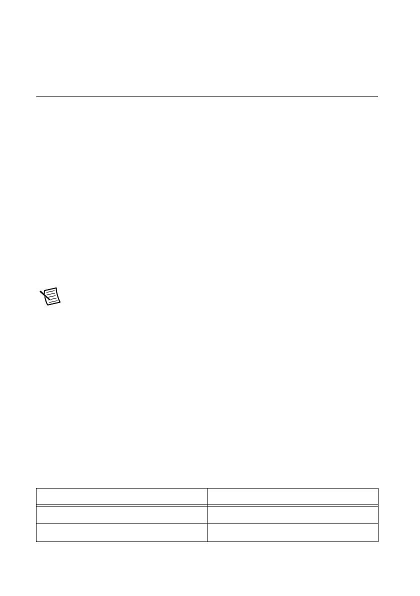
depending on the application the counter is performing. Table 7-8 lists how the terminal is used
in various applications.
Table 7-8. Counter Applications and Counter
n Source
Application Purpose of Source Terminal
Pulse Generation Counter Timebase
One Counter Time Measurements Counter Timebase

 Loading...