1-12 | ni.com
Chapter 1 Getting Started with the cDAQ Chassis
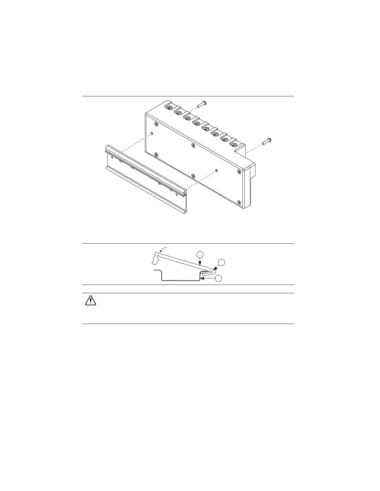
Figure 1-8. cDAQ-9174/9178 DIN Rail Installation
Clip the chassis onto the DIN rail with the larger lip of the DIN clip positioned up, as shown in
Figure 1-9.
Figure 1-9. DIN Rail Clip Parts Locator Diagram
Caution Remove the modules before removing the chassis from the DIN rail.
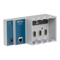
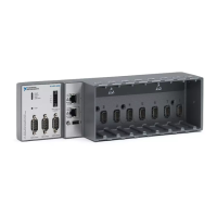
cDAQ Chassis Features
The cDAQ chassis features a chassis grounding screw, USB cable strain relief, and LEDs.
Multislot cDAQ chassis have a power connector and the cDAQ-9178 chassis also features
two TRIG (PFI) BNC connectors. Refer to Figure 1-1, 1-2, or 1-3 for locations of the cDAQ
chassis features.
LEDs
The cDAQ chassis features two status LEDs: ACTIVE and READY. The ACTIVE LED
indicates cDAQ chassis USB bus communication. The READY LED lights when the cDAQ
chassis is ready for use.
1 DIN Rail Clip 2 DIN Rail Spring 3 DIN Rail
1
2
3
Artisan Technology Group - Quality Instrumentation ... Guaranteed | (888) 88-SOURCE | www.artisantg.com
 Loading...