© National Instruments | 5-11
NI cDAQ-9171/9174/9178 User Manual
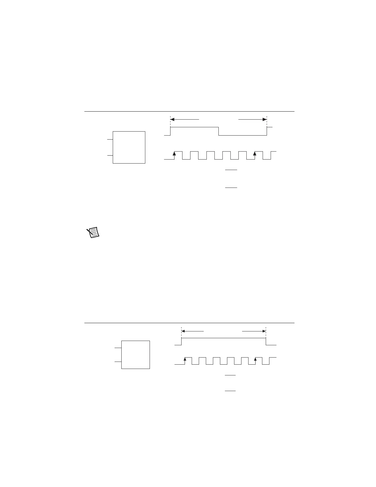
You can configure the counter to measure one period of the gate signal. The frequency of fx is
the inverse of the period. Figure 5-12 illustrates this method.
Figure 5-12. Low Frequency with One Counter
High Frequency with Two Counters
For high frequency measurements with two counters, you measure one pulse of a known width
using your signal and derive the frequency of your signal from the result.
Note Counter 0 is always paired with Counter 1. Counter 2 is always paired with
Counter 3.
In this method, you route a pulse of known duration (T) to the Gate of a counter. You can
generate the pulse using a second counter. You also can generate the pulse externally and connect
it to a PFI terminal. You only need to use one counter if you generate the pulse externally.
Route the signal to measure (fx) to the Source of the counter. Configure the counter for a single
pulse-width measurement. If you measure the width of pulse T to be N periods of fx, the
frequency of fx is N/T.
Figure 5-13 illustrates this method. Another option is to measure the width of a known period
instead of a known pulse.
Figure 5-13. High Frequency with Two Counters
fx
fk
Gate
Source
123 … N
Single Period
Measurement
…
Period of fx =
N
Frequency of fx =
N
Interval Measured
fk
fk
fk
fx
Pulse
fx
Pulse
fx
Gate
Source
12… N
Pulse-Width
Measurement
T =
N
fx
Frequency of fx =
T
Width of
Pulse
N
Width of Pulse (T )
Artisan Technology Group - Quality Instrumentation ... Guaranteed | (888) 88-SOURCE | www.artisantg.com
 Loading...