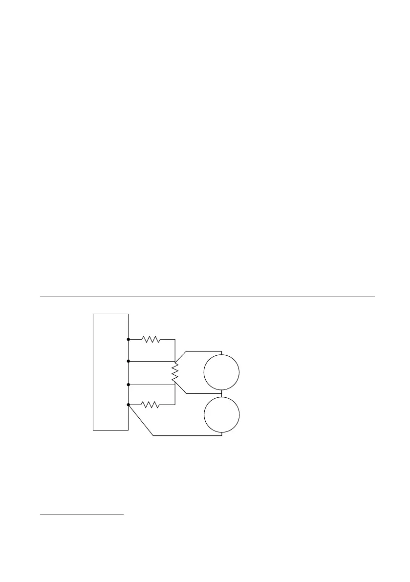
Figure 6. Voltage Remote Sense Output Connection Diagram
NI-DCPower Device
Sense –
Sense +
+
–
Load3
Load 2
Load1
DMM2
Voltage
Mode
+
–
DMM
Load Voltage Measurements
DMM
LO Lead Drop Measurements
DMM1
Voltage
Mode
+
–
2. Set the niDCPower Sense property or NIDCPOWER_ATTR_SENSE attribute to Remote.
3. Set the niDCPower Output Function property or NIDCPOWER_OUTPUT_FUNCTION
attribute to DC Voltage for the NI 4112.
Verifying Voltage Remote Sense Accuracy
Use the NI 4112 in constant voltage mode with a test circuit to simulate the voltage drop
between the device and a load.
Complete this procedure only after successfully completing all previous Verification
procedures.
Refer to the following table as you complete the following steps.
Table 8. Voltage Remote Sense Output Verification
Level
Range
Limit
Range and
Limit
Test
Point
Load
1
Load
2
Load
3
Voltage
Remote
Sense Test
Limit
Minimum
Lead Drop
60 V 1 A 10 V 50 Ω 1 kΩ 50 Ω 0.12% +
55 mV
≥0.4 V
1. Set the first specified level range, limit range, and limit on the NI 4112.
2. Set the level on the NI 4112 to the first specified test point.
3. Measure the LO lead drop with DMM1 from the negative terminal of the device to the
negative side of Load2. Record the measurement as Lead Drop.
4. Verify the Lead Drop measurement is greater than or equal to the minimum lead drop.
5. Measure the load voltage with DMM2 across Load2 where the sense leads connect.
Record the measurement as Load Voltage.
6. Verify the Load Voltage measurement falls within the voltage remote sense test limits.
12 | ni.com | NI PXIe-4112 Calibration Procedure
 Loading...