b) Calculate the lower and upper current measurement test limits using the following
formula:
Current Measurement Test Limits = DMM Measured Current ± (|DMM Measured
Current| × % of Current + Offset)
c) Verify the NI 4112 measurement falls within the test limits.
4. Repeat the previous two steps for each test point specified in the level range.
5. If more than one level range is specified, repeat the previous steps using the values
specified in each level range.
Load Regulation
Connecting and Configuring Equipment for Voltage Load
Regulation Verification
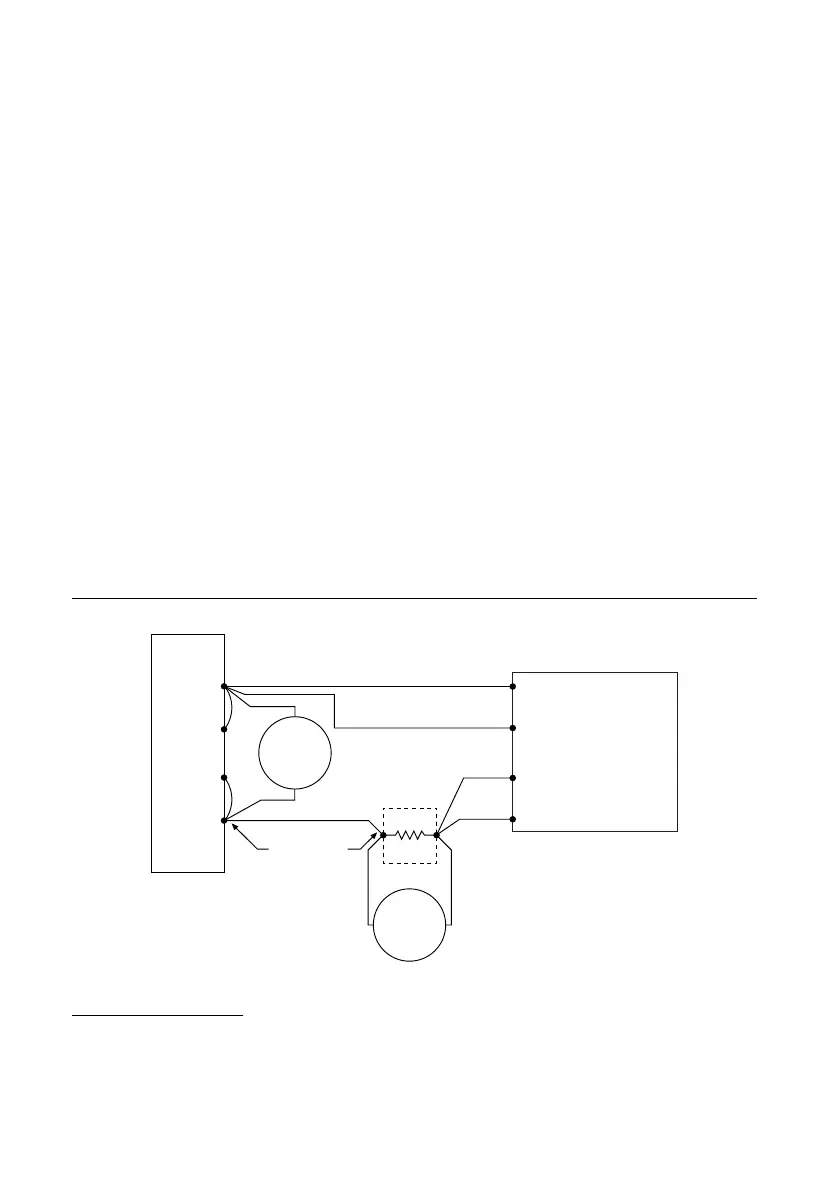
1. Make the necessary connections for this procedure, as shown in the following figure.
Figure 4. Voltage Load Connection Diagram
1
Sense +
+
–
DMM2
Current
Mode
+
–
DMM1
Voltage
Mode
+
–
Electronic Load
Constant Current
Mode
Remote Sense
Mode
Sense +
Ensure cable
resistance <0.1 Ohm
+
–
2. Connect the DMM to the NI 4112 connector pins with dedicated pairs of wires to avoid
including lead drop in the DMM measurement.
3. Set the niDCPower Output Function property or NIDCPOWER_OUTPUT_FUNCTION
attribute to DC Voltage for the NI 4112.
Verifying Voltage Load Regulation
Use the NI 4112 in constant voltage mode to confirm the output voltage change falls within
calculated limits while varying the load current.
Run this test only after successfully verifying voltage output and measurement.
Refer to the following table as you complete the following steps.
1
Configure the electronic load for remote sense mode, and ensure that cables not corrected by
remote sense have a total resistance of <0.1 Ω.
NI PXIe-4112 Calibration Procedure | © National Instruments | 9
 Loading...