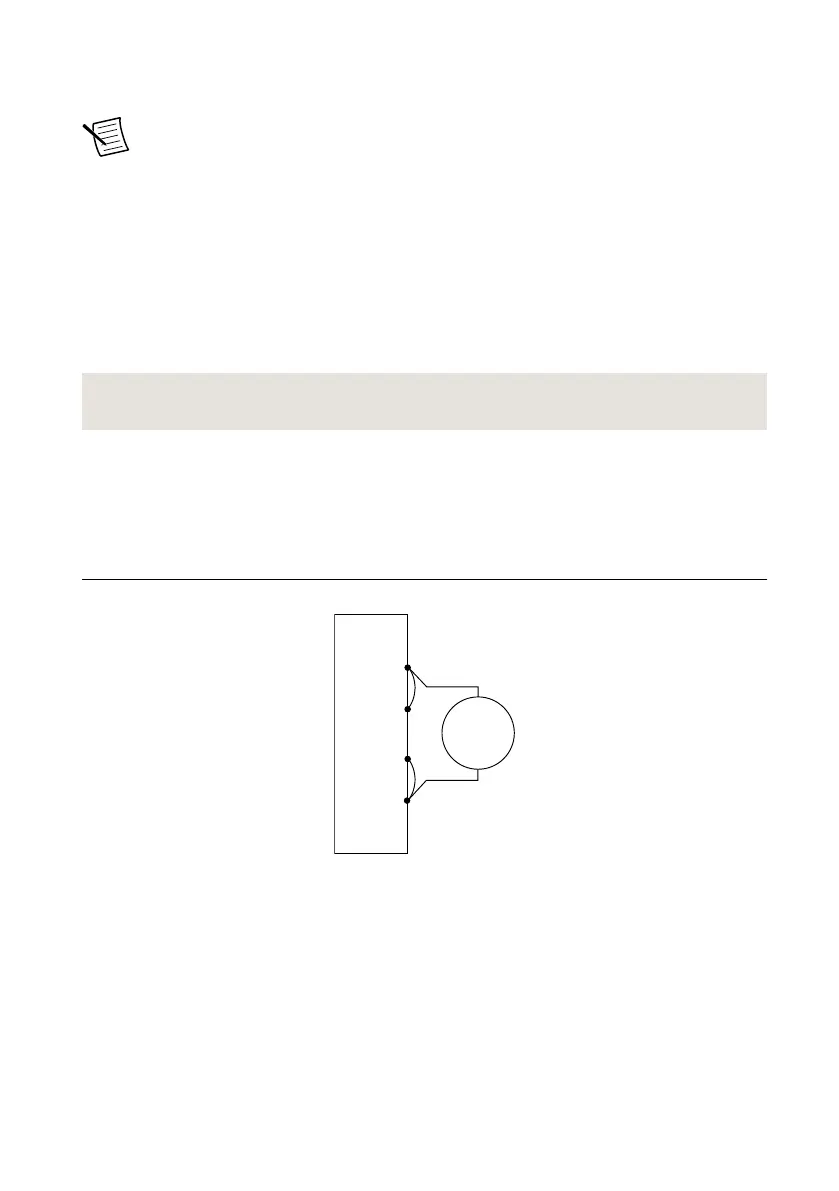
Figure 7. Voltage Verification or Adjustment Connection Diagram
NI-DCPower Device
Sense –
Sense +
+
–
DMM
Voltage
Mode
+
–
2. Set the niDCPower Output Function property or NIDCPOWER_OUTPUT_FUNCTION
attribute to DC Voltage for the NI 4112.
Adjusting Voltage Output and Measurement
Compare a set of voltages measured by the external DMM to both a set of voltage test points
requested by the NI 4112 and to the measured voltages reported by the NI 4112.
Refer to the following table as you complete the following steps.
Table 9. Voltage Output and Measurement Adjustment
Level Range Limit Range and Limit Test Point
60 V 1 A 1.0 V
60 V
1. Set the first specified level range, limit range, and limit on the NI 4112.
2. Set the level on the NI 4112 to the first specified test point.
3. Take a voltage measurement using the DMM, and take a voltage measurement using the
NI 4112.
4. Store the values from the previous step as inputs for the niDCPower Cal Adjust VI or
function called in the following steps.
5. Repeat the previous three steps for each test point specified in the level range.
6. Update the measurement calibration constants by configuring and calling the niDCPower
Cal Adjust Voltage Measurement VI or
niDCPower_CalAdjustVoltageMeasurement function.
a) Input the DMM measurements as the measured outputs.
b) Input the NI 4112 measurements as the reported outputs.
c) Input the specified level range as the range.
14 | ni.com | NI PXIe-4112 Calibration Procedure
 Loading...