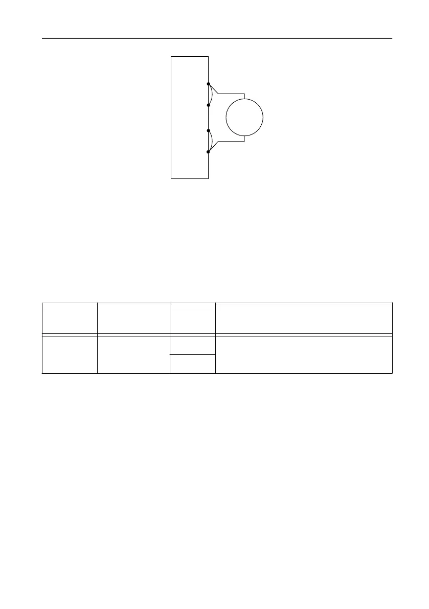
Figure 2. Voltage Verification or Adjustment Connection Diagram
NI-DCPower Device
Sense –
Sense +
+
–
DMM
Voltage
Mode
+
–
2. Set the niDCPower Output Function property or NIDCPOWER_OUTPUT_FUNCTION
attribute to DC Voltage for the NI 4112.
Verifying Voltage Output
Compare a set of voltages measured by an external DMM to the voltage test points requested
by the NI 4112.
Refer to the following table as you complete the following steps.
Table 2. Voltage Output Verification
Level Range Limit Range and
Limit
Test Point As-Found Output Test Limit (% of Voltage +
Offset)
60 V 1 A 0.1 V 0.12% + 55 mV
60 V
1. Set the first specified level range, limit range, and limit on the NI 4112.
2. Set the level on the NI 4112 to the first specified test point.
3. Compare a DMM voltage measurement to the voltage output test limits.
a) Take a voltage measurement using the DMM.
b) Calculate the lower and upper voltage output test limits using the following formula:
Voltage Output Test Limits = Test Point ± (|Test Point| × % of Voltage + Offset)
c) Verify the DMM measurement falls within the test limits.
4. Repeat the previous two steps for each test point specified in the level range.
5. If more than one level range is specified, repeat the previous steps using the values
specified in each level range.
Verifying Voltage Measurement
Compare a set of measured voltages reported by the NI 4112 to the voltages measured by an
external DMM.
Refer to the following table as you complete the following steps.
6 | ni.com | NI PXIe-4112 Calibration Procedure
 Loading...