NI Digital Waveform Generator/Analyzer Guide 24 ni.com
NI 656x Front Panels and Connectors
The NI 656x front panels contain four connectors—three SMB jacks
(CLK IN, PFI 0, and CLK OUT) and one 73-pin 12x Infiniband connector
(DIGITAL DATA & CONTROL, or DDC).
Figure 13 shows the NI 6561 front panels and pinout, which are identical to
those of the NI 6562. Signals marked with an asterisk represent the
complementary terminal for the differential signal of the same name. The
DDC signals are described in Table 3. The SMB connectors are the same as
those described in Table 4, and the LEDs are the same as those described in
Tables 5 and 6.
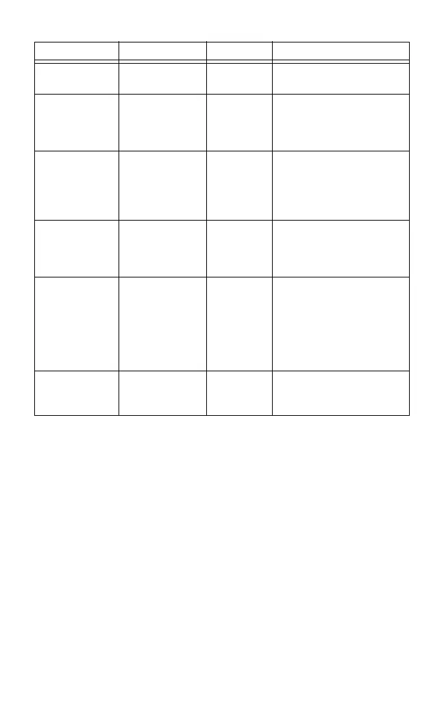
Table 2. NI 655x DDC Connector Pins
Pins Signal Name Signal Type Signal Description
33 DDC CLKOUT Control Output terminal for the
exported Sample clock.
67 STROBE Control Terminal for the external
Sample clock source which
can be used for dynamic
acquisition.
13, 15, 17, 19,
21, 23, 25, 27,
29, 31, 47, 49,
51, 53, 55, 57,
59, 61, 63, 65
DIO <0..19> Data Bidirectional digital I/O data
channels 0 through 19.
26, 30, 64 PFI <1..3> Control Input terminals to the
NI 655x for external triggers,
or output terminals from the
NI 655x for events.
2, 4, 6, 10, 12,
14, 16, 18, 20,
22, 24, 28, 32,
34, 36, 38, 40,
42, 44, 46, 48,
50, 54, 56, 58,
62, 66
GND Ground Ground reference for signals.
1, 3, 5, 7, 8, 9,
11, 35, 37, 39,
41, 43, 45, 52, 60
RESERVED N/A These terminals are reserved
for future use. Do not
connect to these pins.

 Loading...