© National Instruments | B-37
M Series User Manual
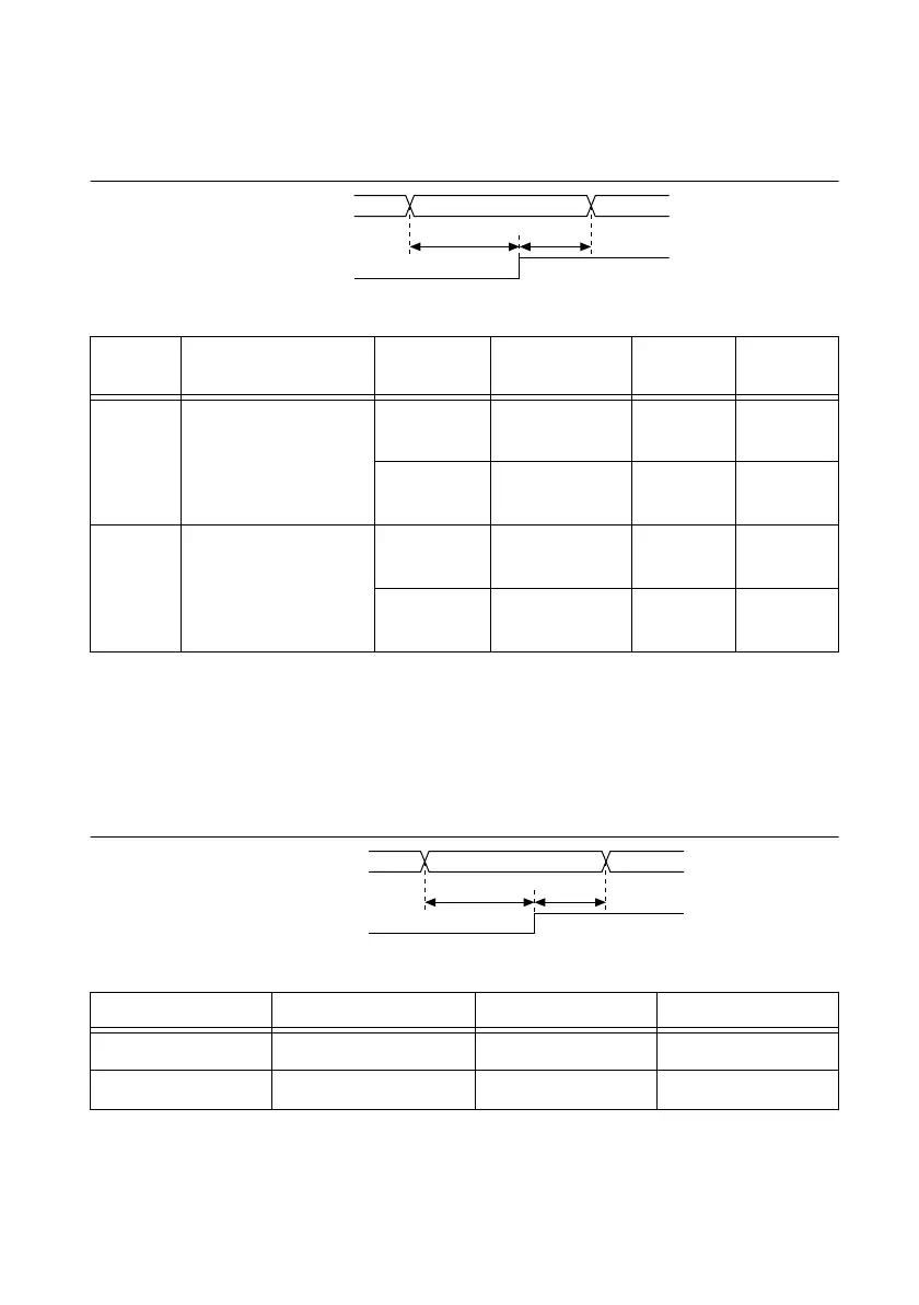
Figure B-48 and Table B-32 show the setup and hold requirements at the PFI pins for the first
case (where a PFI pin drives Counter n Source and a different PFI pin drives Counter n Gate).
Figure B-48. Gate to Source Setup and Hold Timing Diagram
Figure B-49 and Table B-33 show the setup and hold requirements of the internal block of the
DAQ-STC2. Use the table to calculate the setup and hold times for your Source and Gate signals
for the general case. In the general case, you can determine whether the setup and hold
requirements are met by adding up the various delays of the appropriate signals through the
counter/timer circuit.
Figure B-49. DAQ-STC2 Internal Block Setup and Hold Requirements Timing Diagram
Table B-32. Gate to Source Setup and Hold Timing
Time Description
Gating
Mode
Synchronizat
ion Mode
Min (ns) Max (ns)
t
8S
Setup time from PFI
(Gate) to PFI
(Source)
Edge External
Source
12.3 —
Level External
Source
8.3 —
t
8H
Hold time from PFI
(Gate) to PFI
(Source)
Edge External
Source
0.5 —
Level External
Source
2.0 —
Table B-33. DAQ-STC2 Internal Block Setup and Hold Requirements Timing
Time Parameter Min (ns) Max (ns)
t
9S
Setup 1.5 —
t
9H
Hold 0 —
t
8S
t
8H
PFI (Gate)
PFI (Source)
t
9S
t
9H
Count_Enable
Selected_Source
 Loading...


