© National Instruments | B-21
M Series User Manual
the relationship between the two signals depends on the mode of operation. In general, the
Sync Sample Clock Timebase is used to synchronize the input signals to the analog output
timing engine before they are used by the Sample Clock Timebase.
• Start Trigger and Selected Start Trigger—The Start Trigger determines when a timed
analog output operation will begin. This signal can come from a software command or an
external pulse. Selected Start Trigger is the output of the selection block for the Start
Trigger source.
• Pause Trigger and Selected Pause—The waveform generation can be paused using the
pause trigger. When enabled, the waveform generation will occur as long as the gate is
enabled. The generation will be paused if the gate is disabled. This signal can come from a
software command or an external signal. The Selected Pause is the output of the selection
block for the Pause Trigger source.
• Star_Trig, RTSI, or PFI—These terminals are the I/O interface for the device. All
external triggers are input on these terminals. Internal signals can be exported to these
terminals as well.
• _i Signals—All signals marked with _i are external signals that have been through the I/O
buffers and are ready for internal use.
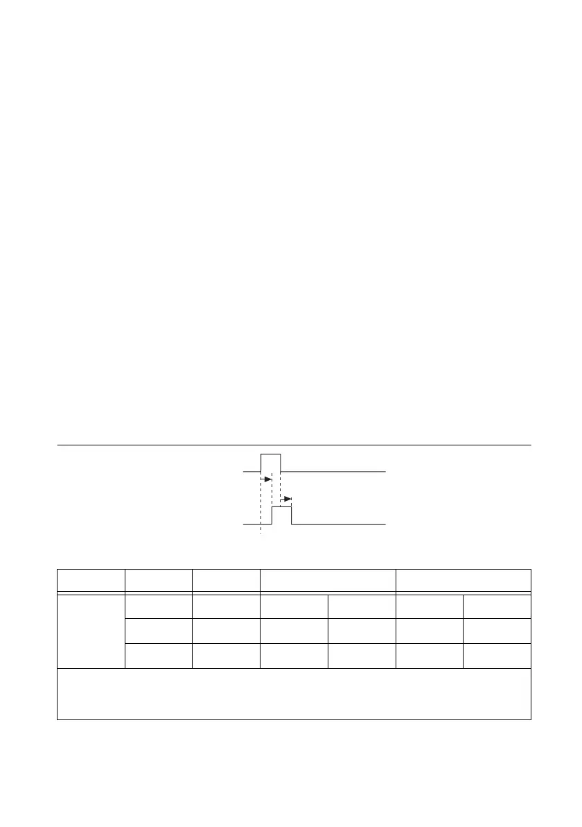
Input Timing
Input timing refers to the delays of importing signals from the external terminals so that the
analog output timing engine can use them as sources for different triggers or clocks. Figure B-23
and Table B-12 describe the insertion delays for external signals.
Figure B-23. Input Timing Diagram
Table B-12. Input Timing
Time From To Min (ns) Max (ns)
t
1
*
PFI PFI_i 4.1 6.4 15.2 19.2
RTSI RTSI_i 0.9 2.2 2.0 3.0
STAR STAR_i 0.9 — — 2.8
*
The delay ranges given for PFI and RTSI represent the fastest and slowest terminal routing within the
trigger group for a given condition (maximum or minimum timing). This difference can be useful when
two external signals will be used together and the relative timing between the signals is important.
 Loading...
