© National Instruments | B-23
M Series User Manual
Start Trigger
As an output, the Start Trigger is routed as an asynchronous pulse. The actual signal that gets
routed is the Selected Start Trigger signal, so there is no synchronous delay involved.
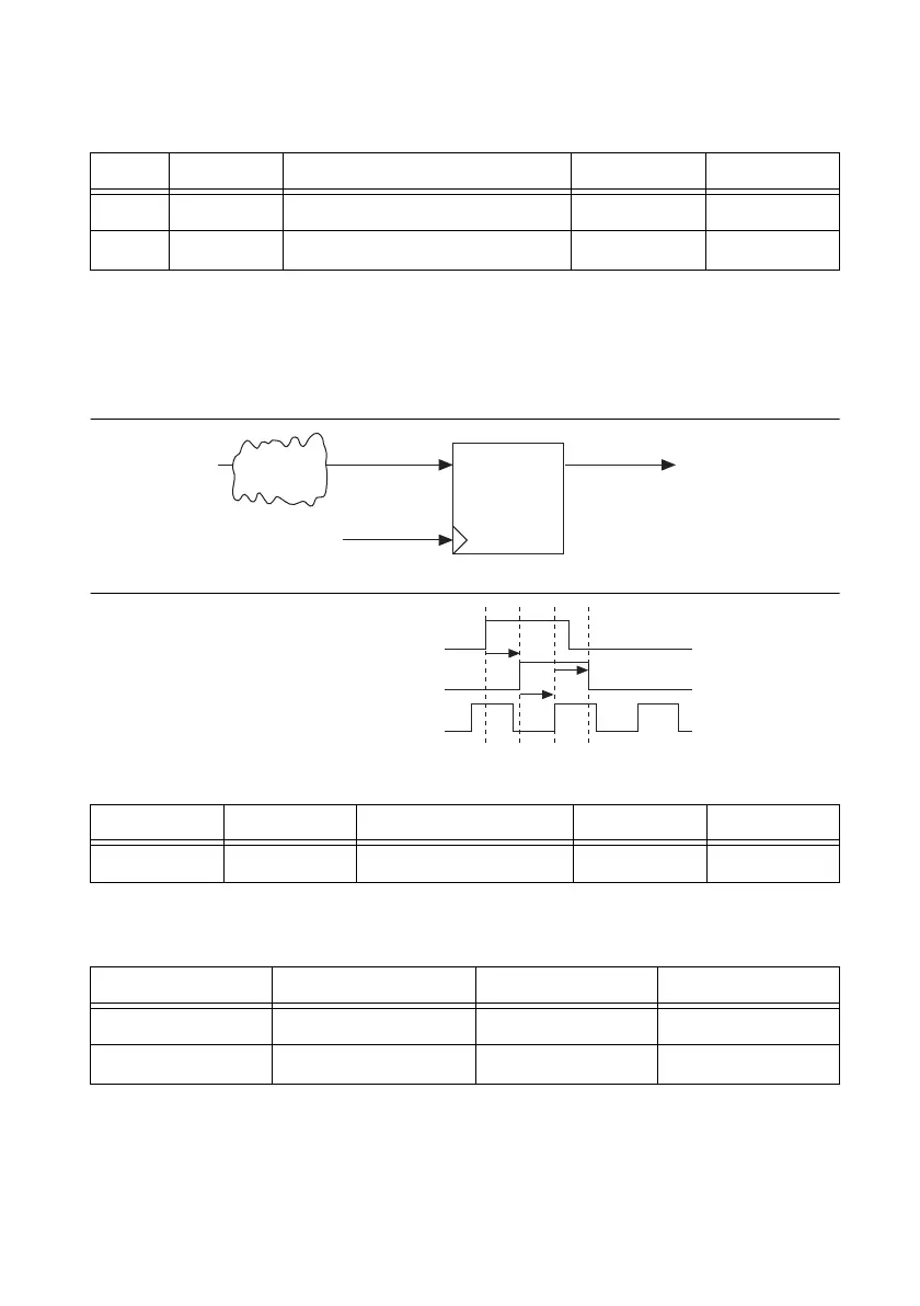
Figure B-26. Start Trigger Input Delay Path
Figure B-27. Start Trigger Timing Diagram
Pause Trigger
The analog output Pause Trigger can be used to pause an ongoing generation. It is received on
the rising edge of Sync Sample Clock Timebase.
Table B-14. Sample Clock Timebase and the Sync Sample Clock Timebase Timing
Time From To Min (ns) Max (ns)
t
4
Signal_i Sample Clock Timebase 2.4 9.3
t
5
Signal_i Sync Sample Clock Timebase 2.4 9.3
Table B-15. Start Trigger Timing from Signal_i to Selected Start Trigger
Time From To Min (ns) Max (ns)
t
6
Signal_i Selected Start Trigger 2.9 9.8
Table B-16. Start Trigger Setup and Hold Timing
Time Parameter Min (ns) Max (ns)
t
7
Setup 1.5 —
t
8
Hold 0 —
Signal_i
Sync Sample Clock Timebase
DQ To Internal Logic
Logic
Selected Start
Trigger
Signal_i
Selected Start Trigger
Sync Sample Clock Timebase
t
6
t
8
t
7
 Loading...
