Chapter 2 Hardware Overview of the NI 78xxR
R Series Intelligent DAQ User Manual 2-20 ni.com
The SHC68-68-RDIO was designed specifically for R Series devices and is
the NI-recommended cable for digital applications. If you are using the
SH68-C68-S cable, however, please note the following considerations.
The SH68-C68-S shielded cable contains 34 twisted pairs of conductors. To
maximize the digital I/O available on the NI 78xxR, some of the DIO lines
are twisted with power or ground and some DIO lines are twisted with other
DIO lines. To obtain maximum signal integrity, place edge-sensitive or
high-frequency digital signals on the DIO lines that are paired with power
or ground. Because the DIO lines that are twisted with other DIO lines can
couple noise onto each other, use these lines for static signals or
non-edge-sensitive, low-frequency digital signals. Examples of
high-frequency or edge-sensitive signals include clock, trigger, pulse-width
modulation (PWM), encoder, and counter signals. Examples of static
signals or non-edge-sensitive, low-frequency signals include LEDs,
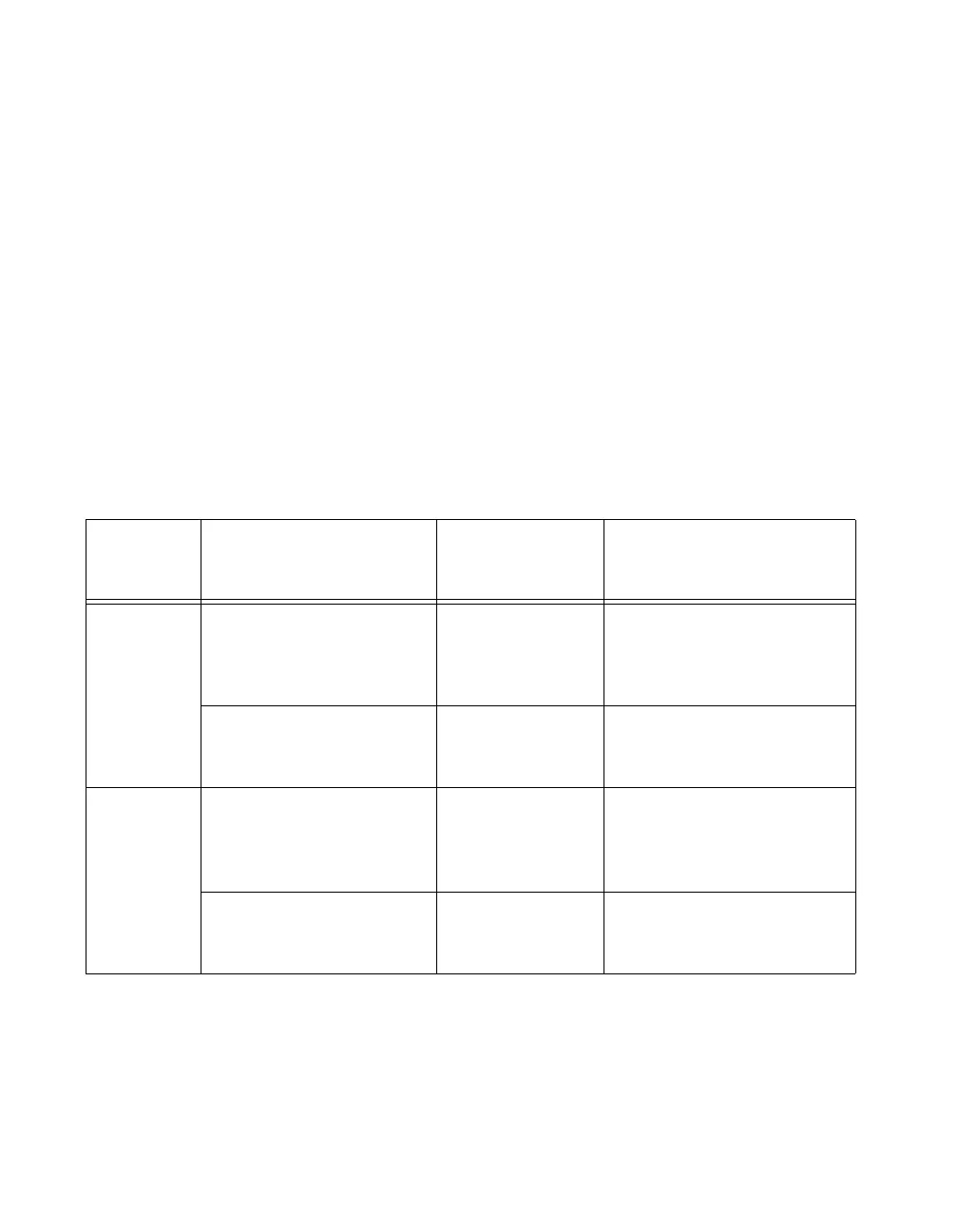
switches, and relays. Table 2-4 summarizes these guidelines.
Table 2-4. DIO Signal Guidelines for the NI 78
xxR
Device Digital Lines
SH68-C68-S
Shielded Cable
Signal Pairing
Recommended Types
of Digital Signals
NI 781xR DIO<0..27> DIO line paired
with power
or ground
All types—high-frequency or
low-frequency signals,
edge-sensitive or
non-edge-sensitive signals
DIO<28..39> DIO line paired
with another
DIO line
Static signals or
non-edge-sensitive,
low-frequency signals
NI 783xR,
NI 784xR,
NI 785xR
Connector 0, DIO<0..7>;
Connector 1, DIO<0..27>;
Connector 2, DIO<0..27>
DIO line paired
with power
or ground
All types—high-frequency or
low-frequency signals,
edge-sensitive or
non-edge-sensitive signals
Connector 0, DIO<8..15>;
Connector 1, DIO<28..39>;
Connector 2, DIO<28..39>
DIO line paired
with another
DIO line
Static signals or
non-edge-sensitive,
low-frequency signals
 Loading...


