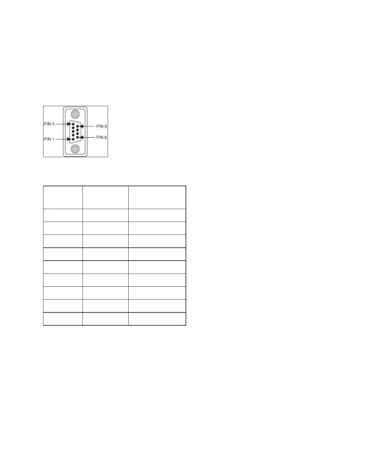
DB-9Connector
Thefollowingfigureandtablegivethepinlocationsanddescriptionsof
theDB-9connector,the10-positionmodularjacktoDB-9cable,the
cableadapterfortheeight-portboard,andtheDB-9connectorstothe
16-portbreakoutbox.
DB-9ConnectorPinLocations
DB-9PinDescriptions
DB-9Pin
232Signal
DTE
485Signal
1 DCD* GND
2 RXD CTS+(HSI+)
3 TXD RTS+(HSO+)
4 DTR* RXD+
5 GND RXD–
6 DSR* CTS–(HSI–)
7 RTS RTS–(HSO–)
8 CTS TXD+
9 RI* TXD–
*Thesesignalsare"NoConnect"ontheisolated232boardsorports9–
16ofthePCI-232/16legacyboard.

 Loading...


