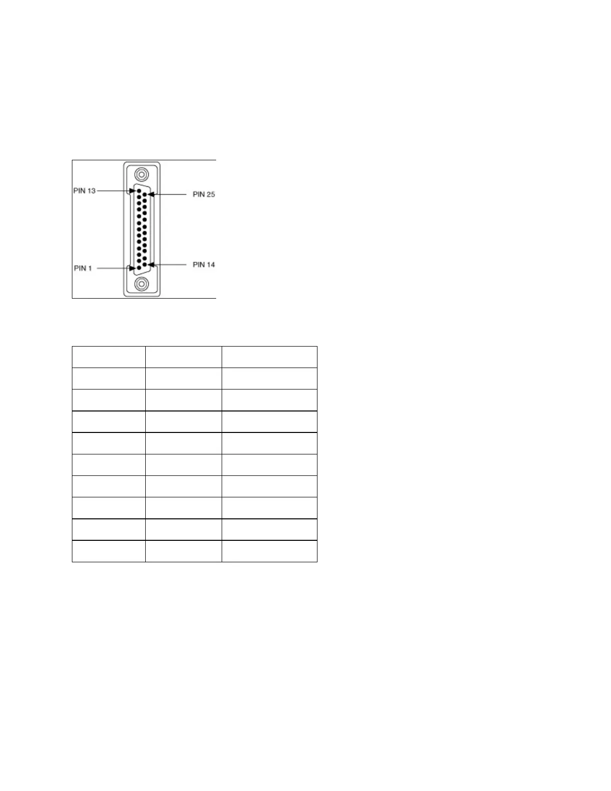
DB-25Connector
Thefollowingfigureandtablegivethepinlocationsanddescriptionsof
theDB-25connector,whichisontheoptional10-positionmodularjackto
DB-25cable.
DB-25ConnectorPinLocations
DB-25PinDescriptions
DB-25Pin 232Signal 485Signal
2 TXD RTS+(HSO+)
3 RXD CTS+(HSI+)
4 RTS RTS–(HSO–)
5 CTS TXD+
6 DSR* CTS–(HSI–)
7 GND RXD–
8 DCD* GND
20 DTR* RXD+
22 RI* TXD–
PinsnotlistedinthistableareNoConnect.
*Thesesignalsare"NoConnect"ontheisolated232ports.
Thefollowingfigureshowshowtoconnectthecableswhenyouinstalla
four-portPXIserialboard.

 Loading...


