22 | ni.com | NI PXI-4110 Calibration Procedure
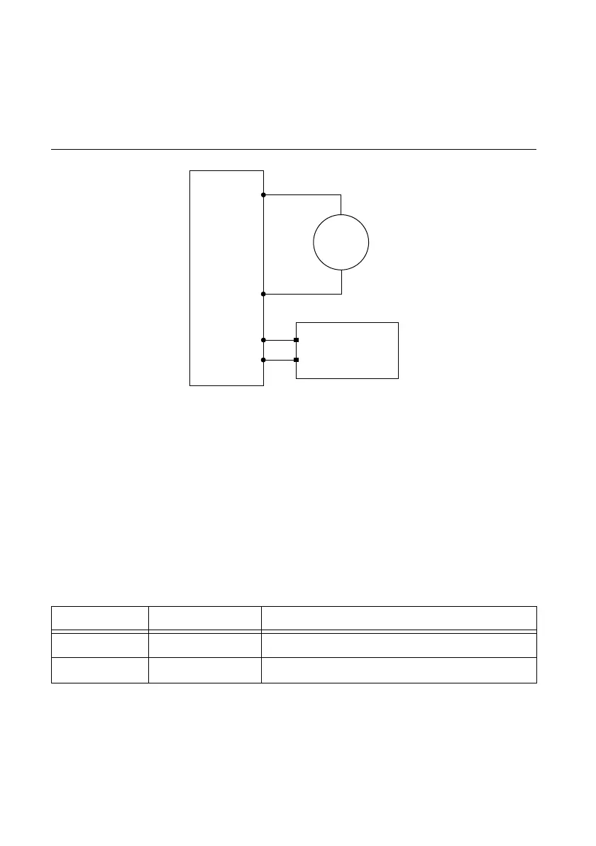
Current Line Regulation
To verify current line regulation, use the NI 4110 in constant current mode and confirm the
output current change falls within calculated limits while varying the line voltage using a
variable power supply. Table 16 lists the voltage values and current measurements needed to
complete verification. Refer to the figure below for the necessary connections.
Figure 7. Current Line Regulation Verification Connection Diagram
Complete the following steps to verify current load regulation:
1. For each test, adjust the external variable power supply to the specified voltage (V
ext1
) listed
in Table 15.
2. Set the NI 4110 to output the current specified in Table 15.
3. Use the DMM to measure the current across the output of the specified channel of the
NI 4110 (I
1
).
4. Change the external variable power supply voltage from V
ext1
to V
ext2
and repeat the
previous step.
5. Record the NI 4110 output current measurements for both external voltages.
6. Calculate the Current Change Limit using the formulas shown in the following table:
Table 15. NI 4110 Current Line Regulation Current Change Limit Formulas
7. Subtract the two voltage measurements I
1
- I
2
to calculate the Current Change. The test
passes if the Current Change falls within the calculated Current Change Limit.
Channels Current Range Current Change Limit
1 and 2 20 mA ± ((I
1
× 1.00 × 10
-4
) + 4.00 × 10
-6
) × (V
ext1
- V
ext2
)
1 and 2 1A ± ((I
1
× 1.00 × 10
-4
) + 2.00 × 10
-4
) × (V
ext1
- V
ext2
)
NI PXI-4110
+
–
HI
LO
DMM
Current
Mode
Variable Power
Supply
+
–
AUX IN +
AUX IN –
 Loading...