4 | ni.com
5. Launch MAX.
6. Expand Devices and Interfaces to confirm that MAX detects the module.
7. Right-click the module name and select Self-Test to ensure that the module is working
properly.
Note When a module is configured with MAX, it is assigned a module name. Each
function call uses this module name to determine which DAQ module to calibrate.
This document uses Dev1 to refer to the module name. In the following procedures,
use the module name as it appears in MAX.
Connecting the Calibrator to the Module
Refer to the specific verification or calibration procedure section for information describing the
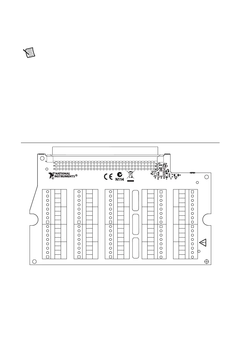
required module connections. Each channel consists of a group of four pins specific to that
channel. Before connecting or disconnecting the calibrator from the module, always set the
calibrator to standby mode (STBY).
Refer to Figure 1 for the pin assignments of the TB-4357.
Figure 1. TB-4357 Pin Assignments
EX–
AI–
AI+
EX–
EX+
AI–
AI+
EX–
EX+
AI–
AI+
EX–
EX+
EX+
AI–
AI+
EX–
AI–
AI+
EX–
EX+
AI–
AI+
EX–
EX+
AI–
AI+
EX–
EX+
EX+
AI–
AI+
EX–
AI–
AI+
EX–
EX+
AI–
AI+
EX–
EX+
AI–
AI+
EX–
EX+
EX+
AI–
AI+
EX–
AI–
AI+
EX–
EX+
AI–
AI+
EX–
EX+
AI–
AI+
EX–
EX+
EX+
AI–
AI+
EX–
AI–
AI+
EX–
EX+
AI–
AI+
EX–
EX+
AI–
AI+
EX–
EX+
EX+
AI–
AI+
C H 0 C H 5 C H 10 C H 15
C H 1 C H 6 C H 11 C H 16
C H 2 C H 7 C H 12 C H 17
C H 3 C H 8 C H 13 C H 18
C H 4 C H 9 C H 14 C H 19
J2 J7
J8J3
J9J4
J10J5
J11J6
TB–4357
152646A–01L
S/N
FOR PATENTS: NI.COM/PATENTS
COPYRIGHT 2011
 Loading...