Table 4. AUX 0 Pin Signal Descriptions (Continued)
Pin Signal Description
15 AUX 0/PFI 5 Bidirectional PFI line
16 AUX 0/PFI 6 Bidirectional PFI line
17 AUX 0/PFI 7 Bidirectional PFI line
18 +3.3 V +3.3 V power output (200 mA maximum)
19 GND Ground reference for signals
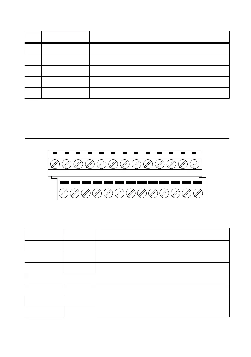
PXIe-5413 SCB-19 Pinout
NI recommends using the SCB-19 connector block to connect digital signals to the AUX 0
connector on the PXIe-5413 front panel. Refer to the following figure and table for
information about the SCB-19 signals when connected to the AUX 0 front panel connector.
1 2
3 4 5
6 7
8 9 10
14 15
16 17 18
19 20
21 22 23
11 12
13
24 25
26
Table 5. SCB-19 Signal Descriptions
Pin Signal Description
1 PFI 0 Bidirectional PFI line
2 PFI 1 Bidirectional PFI line
3 PFI 2 Bidirectional PFI line
4 PFI 3 Bidirectional PFI line
5 NC No connection
6 NC No connection
7 NC No connection
10 | ni.com | PXIe-5413 Getting Started Guide
 Loading...