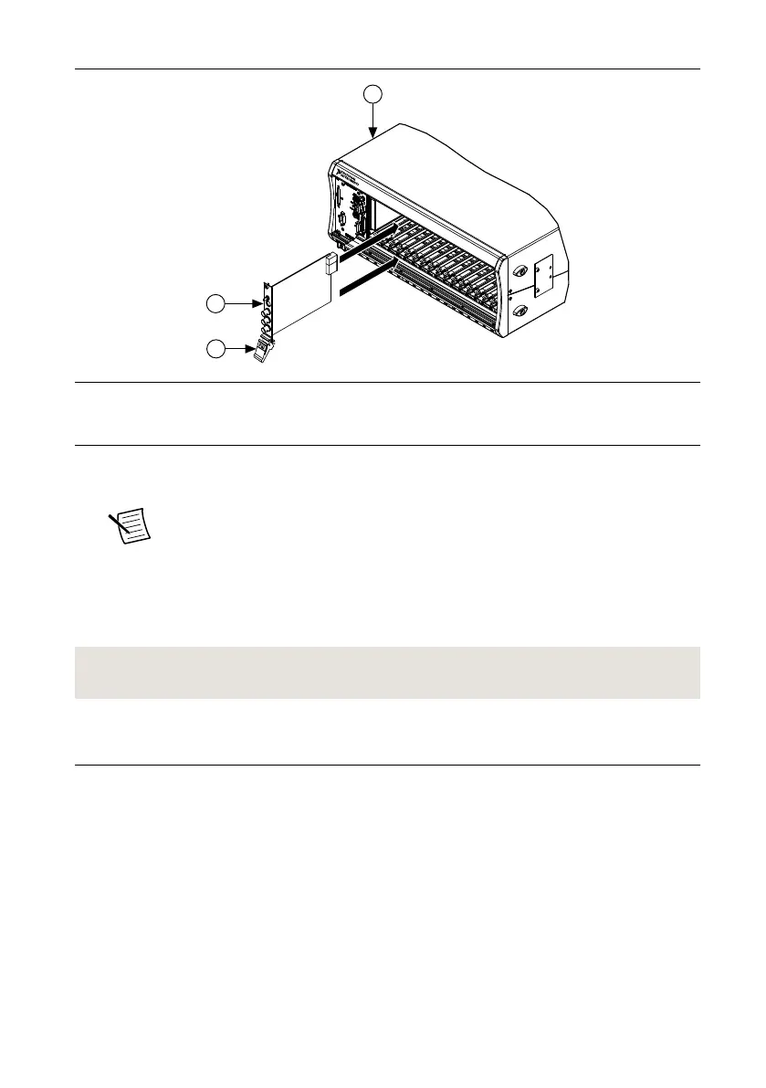
Figure 3. Module Installation
1. Chassis
2. Hardware Module
3. Ejector Handle in Downward (Unlatched) Position
10. Latch the module in place by pulling up on the ejector handle.
11. Secure the module front panel to the chassis using the front-panel mounting screws.
Note Tightening the top and bottom mounting screws increases mechanical
stability and also electrically connects the front panel to the chassis, which can
improve the signal quality and electromagnetic performance.
12. Cover all empty slots using EMC filler panels or fill using slot blockers to maximize
cooling air flow, depending on your application.
13. Power on the chassis.
Related Information
Why Is the ACCESS LED Off When the Chassis Is On? on page 14
PXIe-5413 Pinout and LEDs
Front Panel
Refer to the following figure and tables for information about the one- and two-channel
PXIe-5413 front panel connectors and LEDs.
6 | ni.com | PXIe-5413 Getting Started Guide
 Loading...