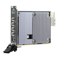
PXIe-5413
20 MHz 16-Bit AWG
ACCESS
ACTIVE
CH 0
50
PFI 1
PFI 0
AUX 0
+5V MAX
PXIe-5413
20 MHz 16-Bit AWG
ACCESS
ACTIVE
CH 0
50
CH 1
50
PFI 1
PFI 0
AUX 0
+5V MAX
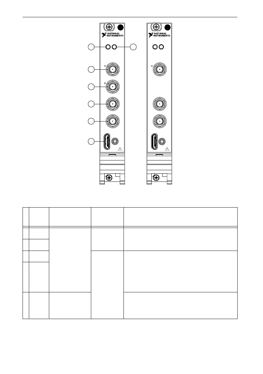
4
5
3
2
1
6
7
Table 1. PXIe-5413 Signal Descriptions
Signal Connector
Type
Access Description
1 CH 0 SMA Output Generates waveforms from an analog output
terminal.
2 CH 1
3 PFI 0 Input/Output Imports digital trigger signals and exports
digital event signals. Imported digital trigger
signals can start or step through waveform
generation, and exported event signals indicate
the state of the generation engine.
4 PFI 1
5 AUX 0 MHDMR Routes digital trigger and event signals with
eight bidirectional PFI lines and provides a
+3.3 V power source.
The ACCESS LED indicates basic hardware status.
PXIe-5413 Getting Started Guide | © National Instruments | 7
 Loading...