© National Instruments | 3-23
RMX Programmable Power Supplies User Manual
External Monitoring of the Operation Status
The J2 connector has status outputs that can be used to externally monitor the operation status
of the RMX programmable power supply. The following five items make up the status outputs.
The outputs are open collector outputs of photocouplers; they are isolated from the internal
circuits of the RMX programmable power supply. The status common is floating (that is, it has
an isolation voltage of less than or equal to 60 V).
The above signal output circuit is protected with reinforced insulation from the MAINS.
The maximum ratings of the signal terminals are as follows:
• Maximum voltage: 30 V.
• Maximum current (sink): 8 mA.
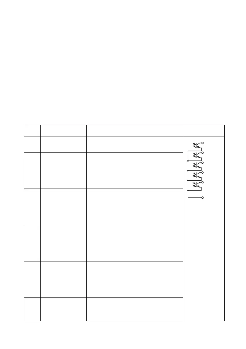
Table 3-4. External Monitoring of the J2 Connector Signal Terminals Operation Status
Pin Signal Description Circuit
6-9 STATUS COM This is the status output common.
This is the photocoupler emitter output.
1 CV STATUS This is set to low level when the RMX
programmable power supply is in constant
voltage mode.
This is the photocoupler open collector
output.
2 CC STATUS This is set to low level when the RMX
programmable power supply is in constant
current mode.
This is the photocoupler open collector
output.
3 ALM STATUS This is set to low level when a protection
function (OVP/OVP2/ OCP/ OHP/ OHP2/
FAN/ SEN/ AC-FAIL/ SD) is activated.
This is the photocoupler open collector
output.
4 PWR ON STATUS This is set to low level when the RMX
programmable power supply is turned on
(PWR ON STATUS).
This is the photocoupler open collector
output.
5 OUT ON STATUS This is set to low level when the output is
turned on. This is the photocoupler open
collector output
1
1
2
3
4
5
6 to 9
 Loading...