3-18 | ni.com
Chapter 3 External Control
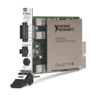
Figure 3-16. Controlling the Output On and Off States.
External Contact Connection
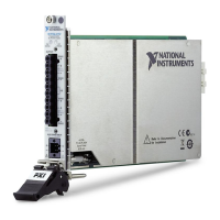
Connect your external contact between pins 18 and 19 of the J1 connector. The open-circuit
voltage across pins 18 and 19 is approximately 5 V. The short-circuit current across pins 18 and
19 is approximately 0.5 mA.
Figure 3-17. External Contact Connection.
Use external contacts that have a contact rating of 0.5 mA or more at 5 VDC. If two or more
units are floating and you are using a single external contact to turn output on and off for all the
units, use a relay or similar device for the external contact signal to isolate the signal transmitted
to each unit.
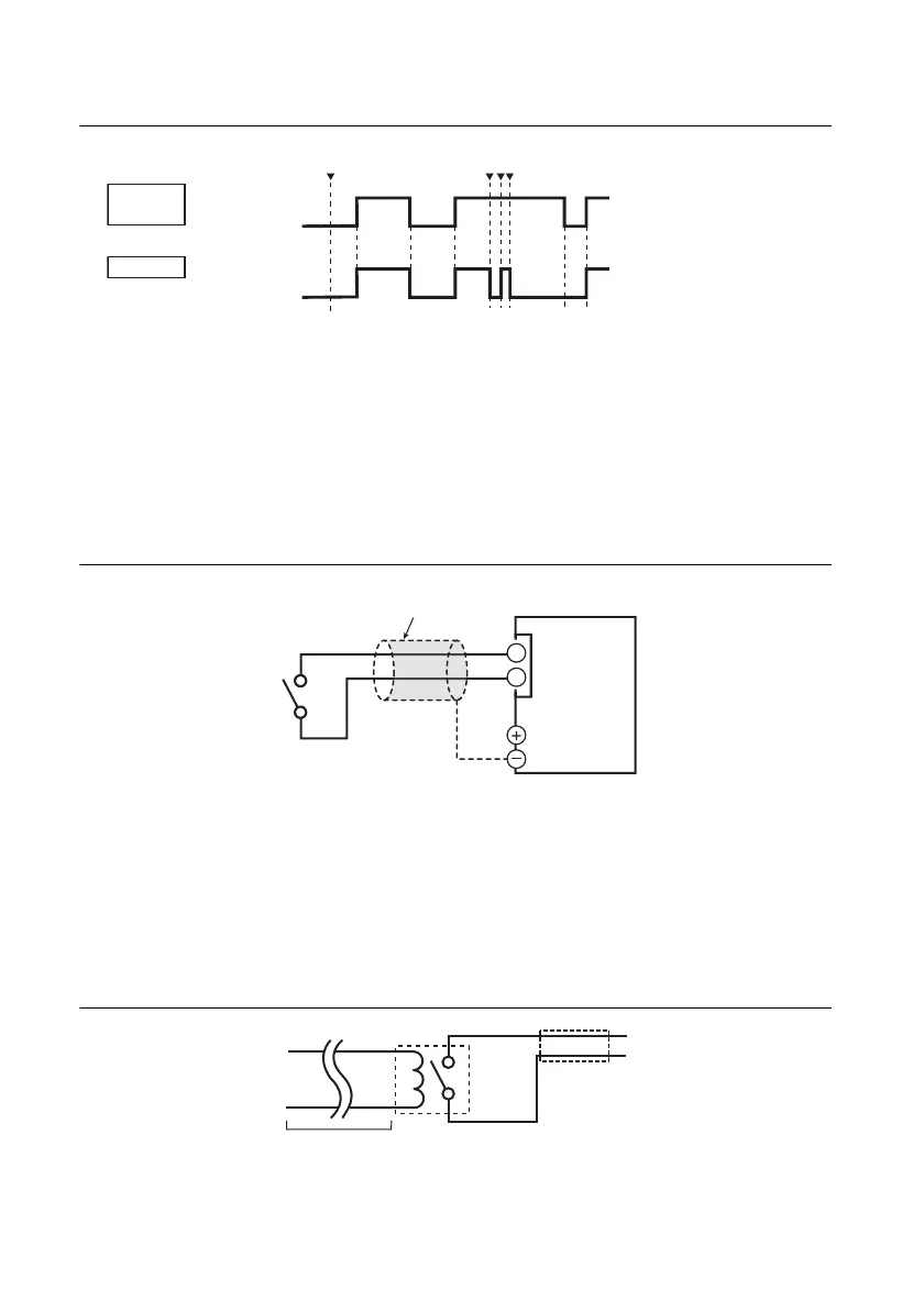
Long-Distance Wiring
When you are wiring over a great distance, use a small relay and extend the coil side of the relay.
Figure 3-18. Long Distance Wiring.
On
Off
H = On
L = Off
▼ represents that the OUTPUT key has been pressed.
The external contact has
been used to turn output
on, so the OUTPUT key
is enabled.
External
contact
The OUTPUT key is
disabled. Even if you
press it, output is
not generated.
To use the external contact to
turn output on again,
first turn the output off.
Output
2-core shielded wire or
twisted-pair wire
Output terminals
J1
18
19
RMX
S
S
Extend this line.
Relay
 Loading...