1-20 | ni.com
Chapter 1 Installation and Preparation
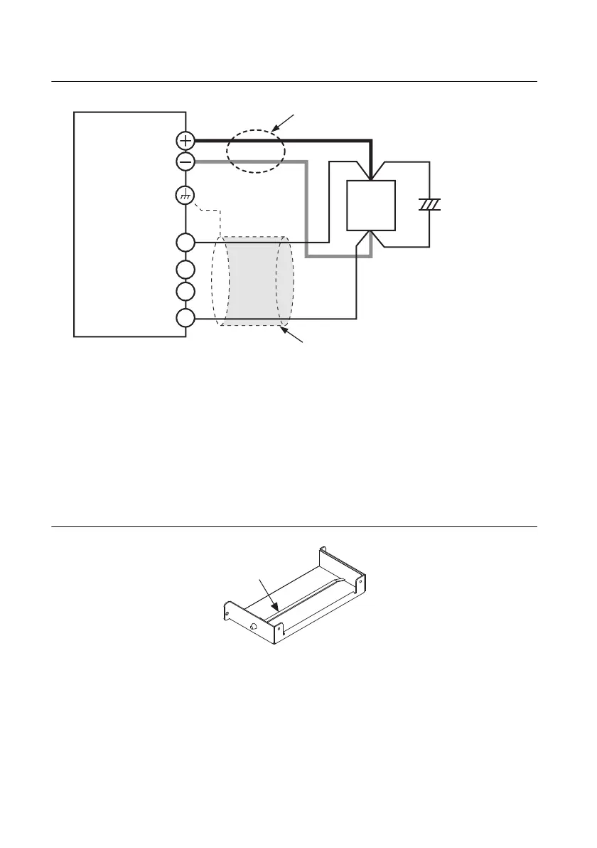
Figure 1-21. Remote Sensing
1. Turn the POWER switch off.
2. Remove the sensing connector from the rear panel sensing terminals.
3. Remove the local sensing jumpers from the sensing connector.
4. Remove 7 mm of the wire covering. Connect the negative sensing cable to -S and the
positive sensing cable to +S.
Use cable screws to securely fix the cables in place so that they do not come loose.
5. Pinch the tip of the band, and remove the band from the connector cover.
Figure 1-22. Bottom Cover with Band
6. As shown in the figure, create a ring 40 mm away from the connector, and fasten with the band.
Make the ring as small as possible, and fasten the band as tight as possible. The band can
be reused. Do not cut the extraneous portion of the band.
+
+
–
–
C
+LS
+S
-LS
-S
Connect an
electrolytic
capacitor
across the load
as necessary.
Output terminal
Chassis terminal
Sensing terminal
RMX
Load
Use twisted-pair wires for the load cables.
Make the cables as short as possible.
For the sensing cables, use twisted-pair
wires or shielded wires.
 Loading...