NV10/NV7.5 Operations and Maintenance Manual Operating the transmitter
Issue 3.4 2016-08-03 Page 2-39
AM-AM and AM-PM correction screens
When the transmitter is operating with digital carriers, the exciter linearizes the transmitter’s
RF drive signal by performing adaptive pre-correction. There are two correction parameters -
AM-AM Correction (see Figure 2.25) and AM-PM Correction (see Figure 2.26 on page 2-40),
which can be viewed as an instrument panel.
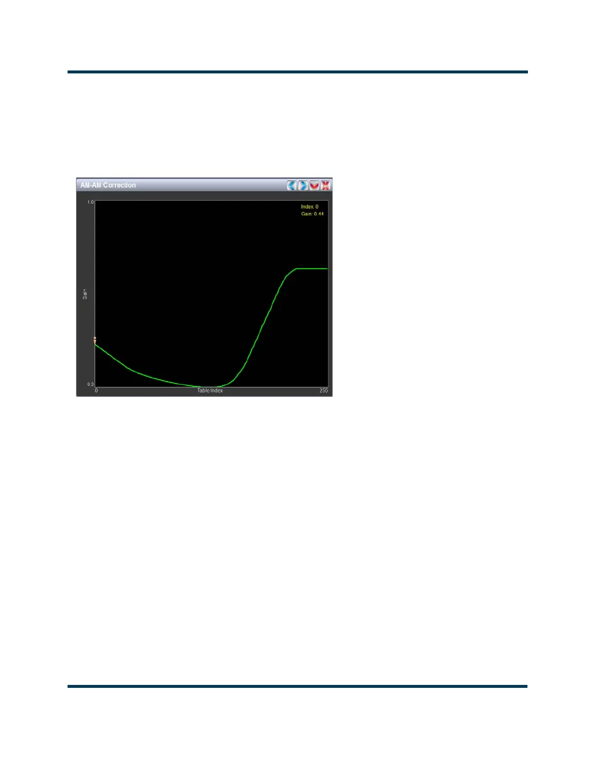
Figure 2.25: AM-AM Correction
AM-AM correction
This panel displays the amplitude correction being applied to the RF drive signal in order to
compensate for the transmitter amplitude (gain) response, which is non-linear. The x-axis
represents the signal amplitude and the y-axis represents the gain correction applied for a given
amplitude value. A look up table (LUT) index value of 0 represents low transmitter output
power (RF drive). A LUT index value of 255 represents the maximum transmitter output
power (RF drive).
The LUT curve can show that at low transmitter output power, more RF drive power is
required to connect for low final stage amplifier gain - the curve sharply increases as it drops to
0 table value. (This low gain can also be overcome using additional bias, however pre-
correction is more efficient.) Equally, the curve could also increase sharply at the top end of
the table, suggesting that high RF drive power (gain) is required to connect for low gain at final
stage amplifiers (PA compression peak limiting). It is technically the inverse of the
transmitter’s power amplifier gain response.