16
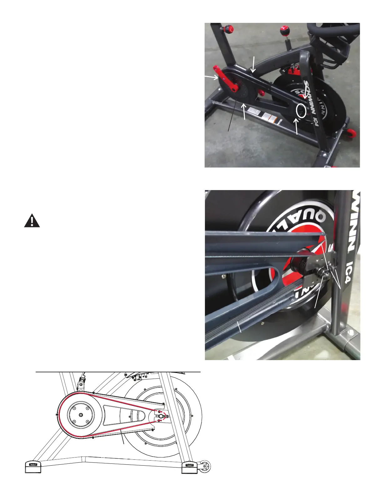
7. Using a #2 Phillips screwdriver, remove the indicated hardware from
the Drive Belt Cover. Carefully remove the Drive Belt Cover and set it
safely aside for reassembly.
Note: The oval indicates the two machine screws with washers.
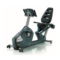
8. Use a 15mm open end wrench to hold the Flywheel Axle Nut on one
side steady and loosen the Flywheel Axle Nut on the opposite side with a
15mm socket and wrench.
Be sure to keep ngers clear of all pinch hazards.
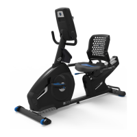
9. Check the tension:
• Push the Drive Belt downward at the midpoint (M) between the pulleys
and measure the distance. The Drive Belt should have only 0.25” (0.64
cm) of give.
Or:
• Hold the edges of the Drive Belt at the midpoint (M) and twist it. It should
turn only 90 degrees (1/4 turn, to vertical).
If the Drive Belt is too loose—use a 10mm wrench to turn each Flywheel
Retainer Nut 1/4 turn to the right.
If the Drive Belt is too tight—use a 10mm wrench to turn each Flywheel
Retainer Nut 1/4 turn to the left.
Drive Belt Cover
Flywheel Axle Nut
Tensioner Eyebolt
Drive Belt
Flywheel
Retainer
Nuts
M
Note: Please disregard the Right Crank Arm in the above
image. It was removed during an earlier step.