17
10. Reinstall the right Crank Arm and Pedal. Installation does not require
the use of the crank puller. Be sure the Crank Arms are connected at 180°
from each other.
11. Get on the bike and check the movement of the Drive Belt by rocking
back and forth on the pedals. The Pedals and Flywheel should move as
one.
Adjust the Drive Belt tension again if necessary.
12. Tighten the Axle Nuts when the Drive Belt tension is correct.
NOTICE: Make sure the Flywheel is aligned with the Frame. Be
sure the Flywheel Axle does not touch the Drive Belt
inside.
13. Remove the right Pedal and Crank Arm. Reinstall the Drive Belt
Cover, Crank Arm and Pedal.
14. Add Loctite
®
272 (or equivalent) to the inner threads of the Crank
Nuts. Do not to apply the Loctite
®
272 to the Crank Shaft.
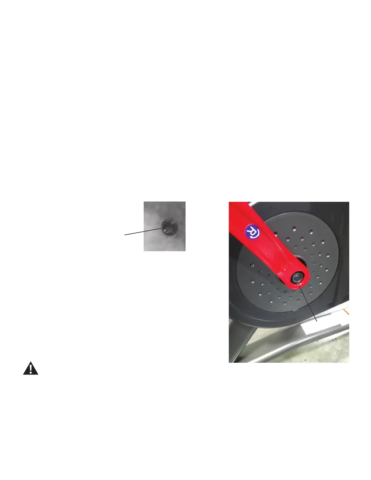
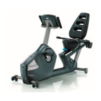
15. Install the Crank Nut onto the Crank Shaft, and fully tighten it.
16. Replace the threaded Cap onto the Crank Arm.
17. Final Inspection
Inspect your machine to ensure that all hardware is tight and components
are properly assembled.
Do not use until the machine has been fully assembled and
inspected for correct performance in accordance with the
Owner’s Manual.
Crank Nut
Crank Nut