62
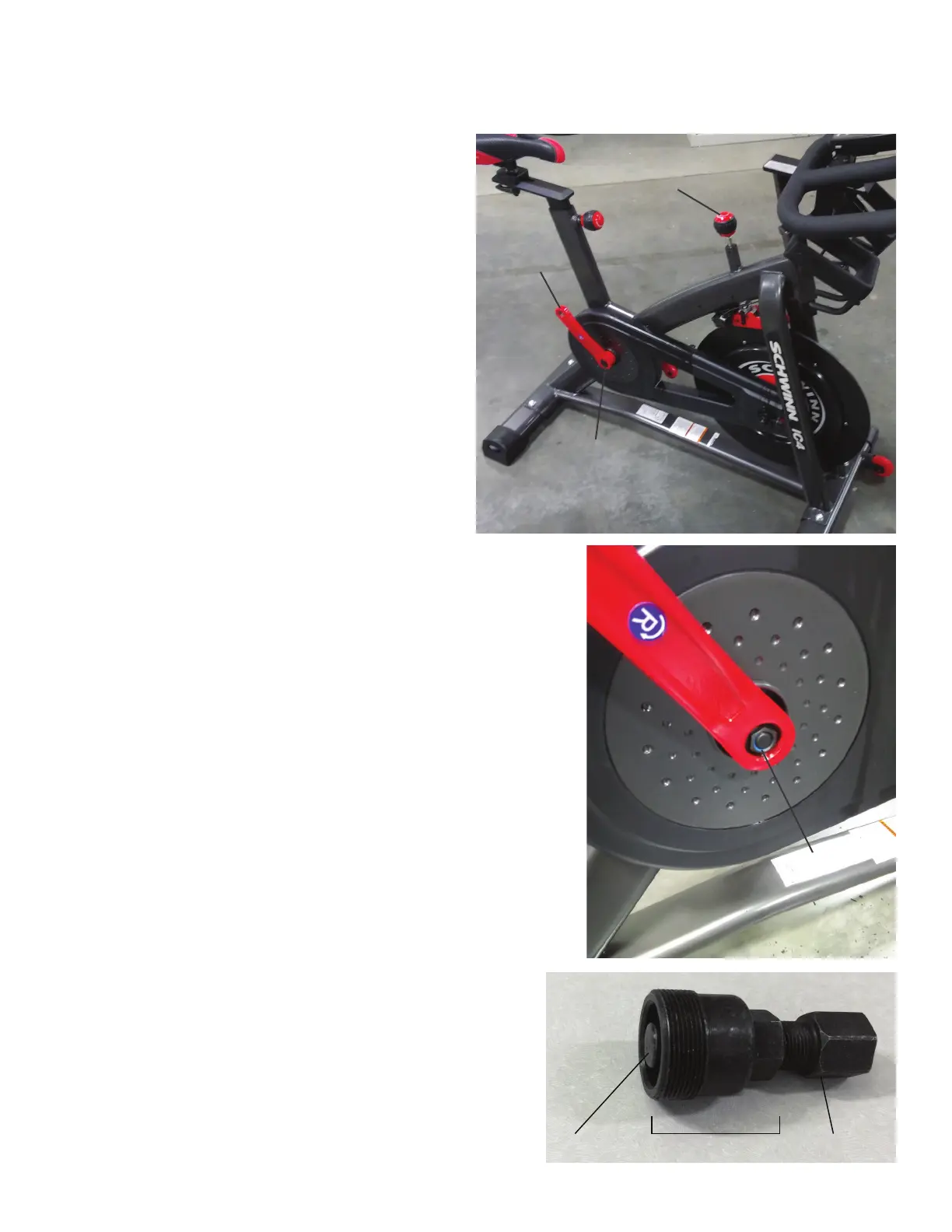
2. Fully turn the Resistance Knob clockwise to lock the Flywheel into
place.
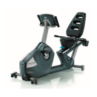
3. Using a athead screwdriver, remove the threaded Cap from the
right Crank Arm.
4. Using a 16mm socket and wrench, remove the Crank Nut under
the threaded Cap.
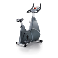
5. Thread the Crank Puller into the Crank Arm (A). When the Crank
Puller is in the correct position, only 1-2 threads on the outer portion
(CP2) of the Crank Puller should show.
Note: Be sure the end of the Bolt (CP1) in the Crank Puller is ush
with the inner surface (CP2) as shown, before use.
6. Using a 15mm wrench, turn the inner portion (CP3) of the Crank
Puller clockwise. The Crank Arm will slide off as it is tightened.
NOTICE: At the end of this procedure, make sure that the Drive Belt tension is correct. Refer to the “Adjust the Belt Tension” procedure.
Note: Your machine may not match the images provided exactly.
1. Unplug the AC Adapter from the wall outlet and machine.
CP1 CP2 CP3
Cap
Crank Arm
Crank Nut
Resistance Knob