81
Fender
7. Re-install all remaining parts that were removed in reverse order.
NOTICE: Do not crimp any cables.
Re-install the Fender, making sure the Resistance Cable is routed
between the Frame and the top of the Fender.
8. Plug the AC Adapter from the wall outlet to the machine.
9. With the Console activated and in Power-Up mode, push the START/
ENTER button.
10. Within 5 seconds of completing Step 9, push and hold down the
Reset and Increase buttons for 3 seconds. The Console is now in Service
Mode.
11. Now push and hold down the Reset and Increase buttons again for
3 seconds. The Console is now in the Calibrate the Magnetic Resistance
Sensor option (display with placeholders shown).
12. The Console displays four values with one of them ashing.
Note: The Magnetic Resistance Sensor can only be calibrated three
times. If the Console displays the Calibration Round as “3”, then it cannot
be calibrated again.
The upper value is the current position supplied by the Resistance Knob.
This is the value controlled by the user.
The 1% Congured Value is the previously calibrated position for the 1%
Resistance Value. This value is the rst to be calibrated and is the one
ashing.
Turn the Resistance Knob counter-clockwise until it is unable to turn, and
then turn it clockwise a quarter of a turn.
13. Push the START/ENTER button to set this value as the new 1%
Congured Value. The Console will update the displayed value.
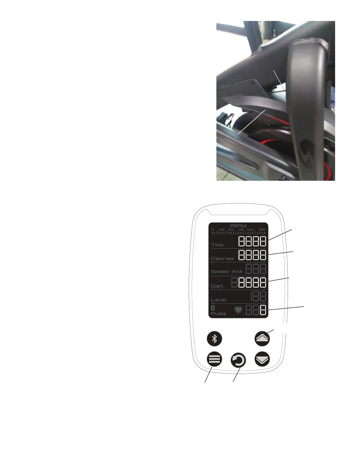
Resistance Cable
Fender
™
START/
ENTER
button
Reset button
Increase button
Current position
value
1% Congured
Value
100% Congured
Value
Calibration
Round