108
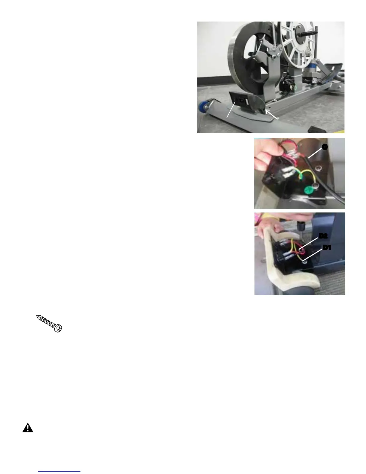
16. Loosen and remove the two screws (one indicated with an arrow) that
attach the back cover of the Power Switch assembly to the sides of the
Frame. Remove the back cover.
NOTICE: Do not crimp the cables.
Note: Your machine may not match the image. For reference only.
17. Carefully disconnect the Power Inlet cable (C) from the Power Switch
assembly.
18. Loosen and remove the screws (D1, D2) that attach the Power
Inlet bracket to the Frame. Remove and discard the old Power Switch
assembly.
19. Installation is the reverse procedure.
Note: Use screw D1 to attach the green ground wire to the bracket and
Frame. Be sure not to crimp any cables.
PuttheLeftShroudinpositionrsttoalignthescrewsfortheRight
Shroud.Installthetopscrewsrst.BesurethetabsintheMotorizedLift
Cover snap into the Side Shrouds.
NOTICE: This step may require two people. Be sure not to crimp
any cables.
Note: Self-tapping screws attach the Shrouds to the Frame.
Installation does not require the use of the crank puller. Be sure the Crank
Arms are connected at 180° from each other.
20. Dispose of the old parts.
21. Inspect your machine to ensure that all hardware is tight and
components are properly assembled.
Do not use until the machine has been fully assembled and
inspected for correct performance in accordance with the
Owner’s Manual.
Power Switch
C
D2
D1
 Loading...