129
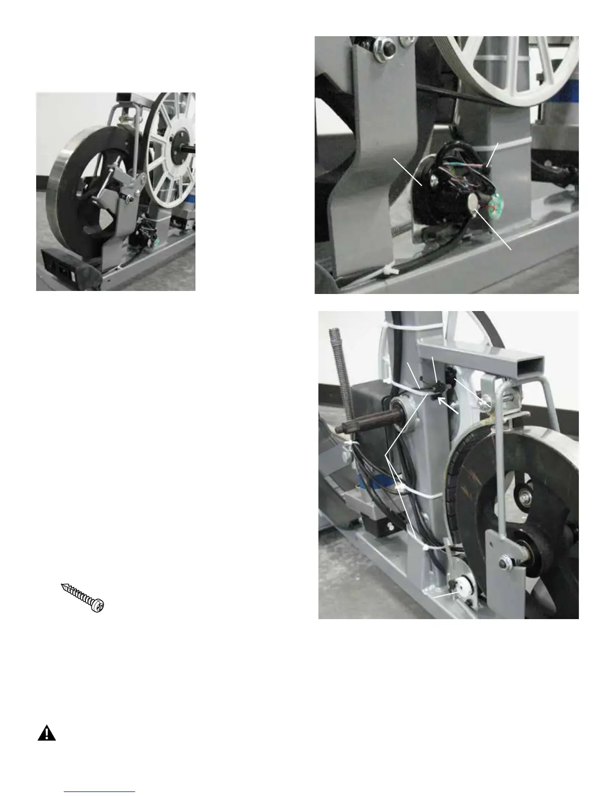
13. Disconnect the Speed Sensor Cable from the Servo Motor wiring
harness.
NOTICE: Do not touch the Potentiometer. Do not crimp any cables.
14. Observe the cable routing from the Speed Sensor Magnet to the
Servo Motor wiring harness.
15. Remove the zip ties that attach the Speed Sensor Cable to the Frame.
NOTICE: Do not crimp the cables.
16. Using a #2 Phillips screwdriver, remove the indicated screw (by arrow)
from the Speed Sensor Magnet.
17. Installation is the reverse procedure.
Note:PuttheLeftShroudinpositionrsttoalignthescrewsforthe
RightShroud.Installthetopscrewsrst.Besurethetabsin
the Motorized Lift Cover snap into the Side Shrouds.
NOTICE: This step may require two people. Be sure not to crimp
any cables.
Note: Self-tapping screws attach the Shrouds to the Frame.
Installation does not require the use of the crank puller. Be sure the Crank
Arms are connected at 180° from each other.
18. Dispose of the old parts.
Speed Sensor
Speed Sensor
Magnet
Speed Sensor Cable
Connection
Servo Motor
Potentiometer
Speed Sensor Cable
Servo Motor
Zip Ties
19. Inspect your machine to ensure that all hardware is tight and components are properly assembled.
Do not use until the machine has been fully assembled and inspected for correct performance in accordance with the Owner’s
Manual.

 Loading...