35
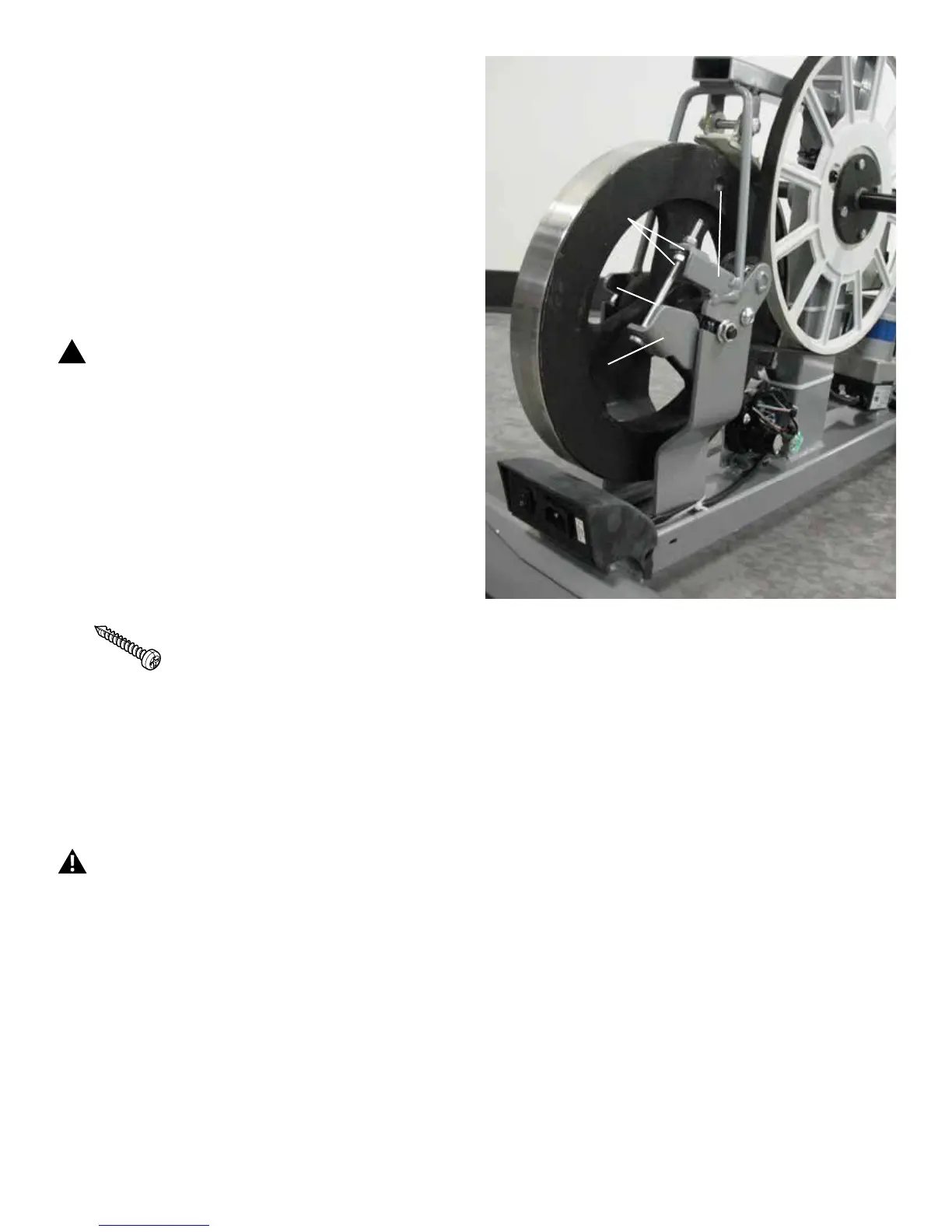
Tensioner Assembly
Tensioner Bracket
Tensioner Nuts
Tensioner Bolt
18. To adjust the Tensioner Nuts on the Tensioner Bracket, use
a 10mm open end wrench to hold the Tensioner Bolt steady and
turn the nuts with a second 10mm open end wrench.
19. When the tension is correct, tighten the nuts against the
Tensioner Bracket to hold the bolt and the Tensioner Assembly
in position.
Note: This step may require two people.
20. Carefully turn the Right Crank Arm and check the movement
of the Drive Belt. The Crank Arms and Flywheel should move as
one.
!
Be sure to keep ngers clear of all pinch hazards
when you turn the Right Crank Arm.
Adjust the belt tension again if necessary.
21. Installation is the reverse procedure.
PuttheLeftShroudinpositionrsttoalignthescrewsforthe
RightShroud.Installthetopscrewsrst.Besurethetabsinthe
Motorized Lift Cover snap into the Side Shrouds.
NOTICE: This step may require two people. Be sure not to
crimp any cables.
Note: Self-tapping screws attach the Shrouds to the Frame.
Installation does not require the use of the crank puller. Be sure
the Crank Arms are connected at 180° from each other.
22. Inspect your machine to ensure that all hardware is tight
and components are properly assembled.
Do not use until the machine has been fully assem-
bled and inspected for correct performance in
accordance with the Owner’s Manual.
 Loading...