88
30. Push the Down arrow button 2 times to go to the MOVE LIFT option
and push OK to enter the lift options menu.
31. The console displays the UP MX DN MN RT CAL prompt. Push the
Down arrow so that the Lift Motor turns to the lower limit.
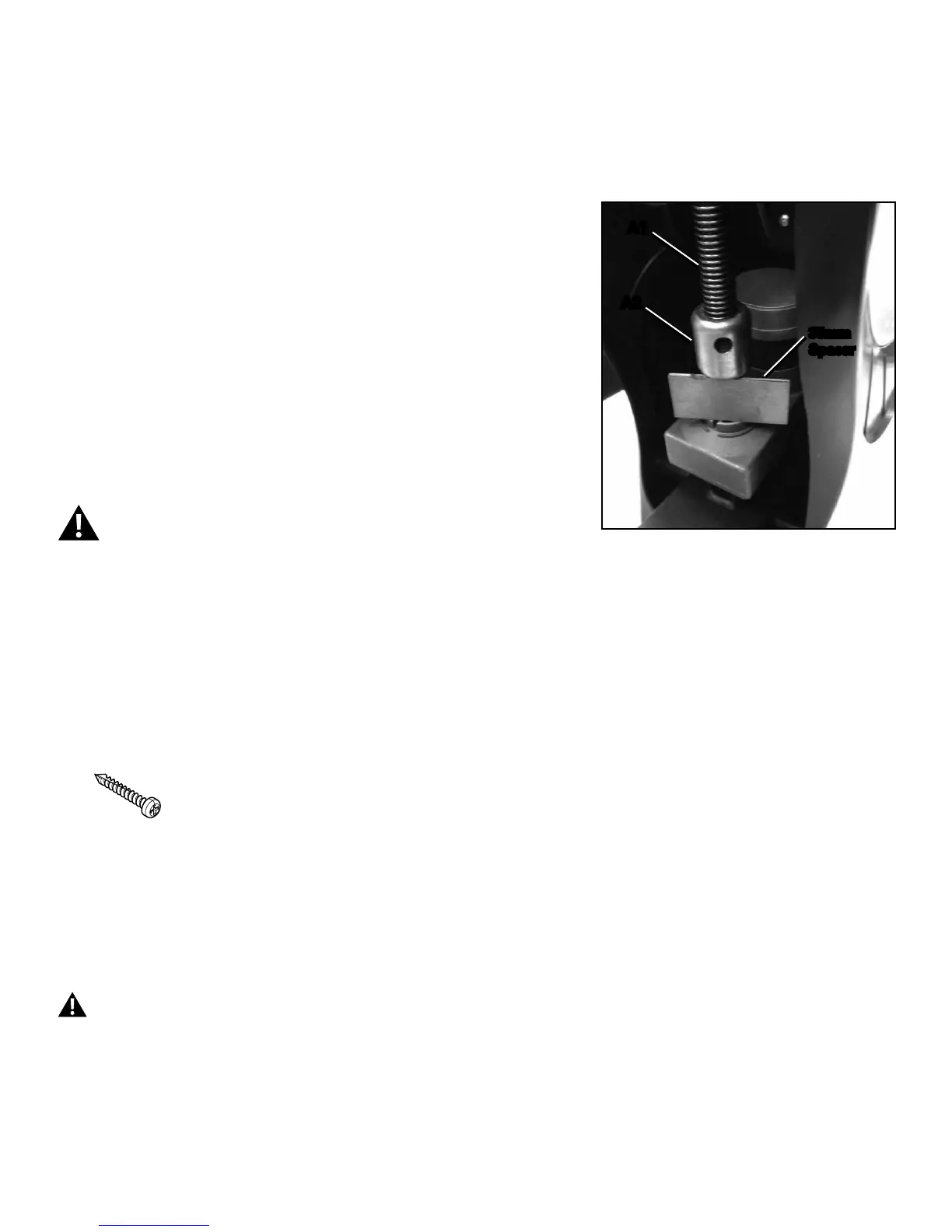
32. When the motor has stopped turning, adjust the nut (A2) on the shaft
(A1) to 35mm above the Lift Motor base, using a ruler or 35mm spacer.
33. Adjust the nut (A2) upward away from the motor base until the holes
in the nut align with the holes in the Incline Adjuster (J) bracket. Install the
hexheadbolts(K)tosecurethebrackettothenut.
34.PushtheOKbuttontoexittheMOVELIFToption.PushPAUSE/END
to go back to the Power-Up Mode screen.
35.Pushthe100%liftpresetbuttontoconrmcorrrectoperation.Push
the0%liftpresetbuttontoconrmcorrectoperation.
Disconnect all power and allow to sit for 5 minutes.
A1
A2
35mm
Spacer
36. Reassembly is the reverse procedure. Secure the cables with zipties.
NOTICE: Do not crimp the cables.
PuttheLeftShroudinpositionrsttoalignthescrewsfortheRightShroud.Installthetopscrewsrst.
NOTICE: This step may require two people. Be sure not to crimp any cables.
Note: Self-tapping screws attach the Shrouds to the Frame.
Be sure the tabs in the Motorized Lift Cover snap into the Side Shrouds.
Installation does not require the use of the crank puller. Be sure the Crank Arms are connected at 180° from each other.
37. Inspect your machine to ensure that all hardware is tight and components are properly assembled.
Do not use until the machine has been fully assembled and inspected for correct performance in accordance with the Owner’s
Manual.
 Loading...