35
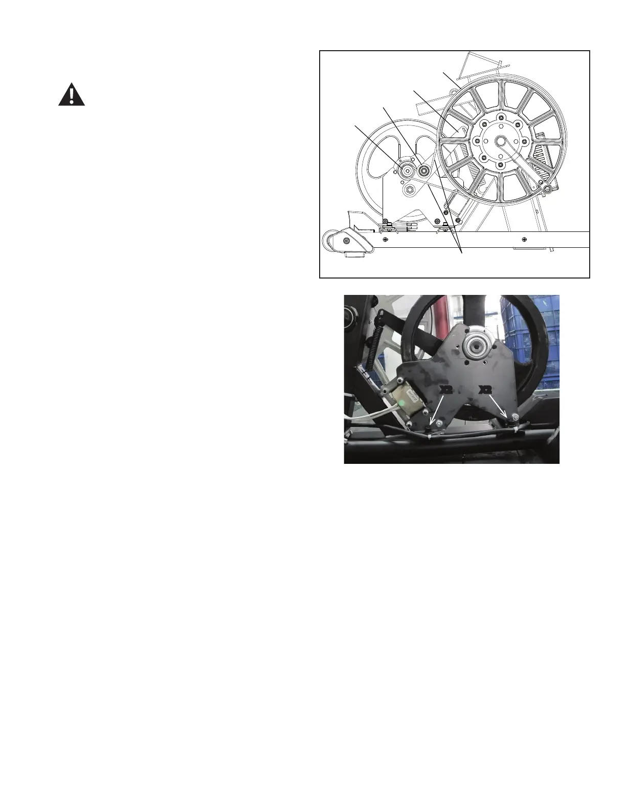
6. Slowly turn the Drive Pulley (B) backward and carefully
ease the Drive Belt (C) to the outside to remove it from the
Flywheel Pulley (D) and Tensioner Assembly pulley (E).
%HVXUHWRNHHS¿QJHUVFOHDURIDOOSLQFK
KD]DUGVDV\RXWXUQWKH'ULYH3XOOH\
7. 8VLQJDPPKH[ZUHQFKUHPRYHWKHLQGLFDWHG
screws and washers (with arrows) that secure the EMS
Engine to the Frame. Set the hardware aside for reassembly.
Slowly remove the EMS Engine.
8. Put the new EMS Engine in position on the Frame and
install the hardware.
9. Put the Drive Belt (C) in position on the Flywheel Pulley
(D) and the Tensioner Assembly pulley (E). Be sure that
the upper portion of the Drive Belt is under the Tensioner
Assembly pulley.
10. Make sure the Drive Belt (C) is aligned on the Flywheel
Pulley (D), Tensioner Assembly (E) and Drive Pulley (B).
11. Using needlenose pliers, attach the Belt Tensioner
spring (A) to the Frame and Tensioner arm (F). Make sure
that the belt tension is correct. Refer to the “Belt Tension
Adjustment” section in this manual.
Note: This step may require two people.
12. Connect the EMS Cable to the EMS MCB Watts
assembly and secure it with a ziptie.
NOTICE: Do not crimp the cables.
R628 left side view
B
E
D
C
)
; ;
 Loading...